Stamp communicating over serial cable and XBee's to PLC - updated with more wir
·Hi folks.
·A lot of my projects·are industrial control systems and many of them require communication among different devices.
·In a recent PLC (Programmable Logic Controller) course I taught, the PLC I chose for the trainers was the new KOYO CLICK series. Very inexpensive, free software and extensive hardware features, including two serial ports and commands for moving data around the registers. After the course, I thought it might be a neat exercise to get the Stamp and the PLC to communicate.
·The Stamp runs a small program that sends out 3 address characters, followed by a byte which is tracking a counter that gets updated about once a second. When the PLC· gets the byte, it displays the value in binary on the lights connected to its outputs. Then, the PLC reads its inputs (1 NO pushbutton, 1 NC pushbutton, and a 2-position selector switch) and sends that back to the Stamp. The Stamp displays that value in binary on its low order·byte (OUTL). The Stamp program is attached. Also attached is a pdf of the ladder logic program running in the CLICK PLC.
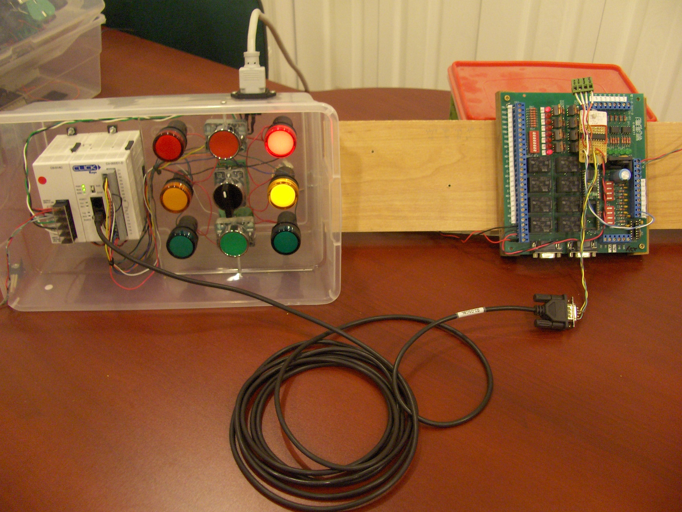
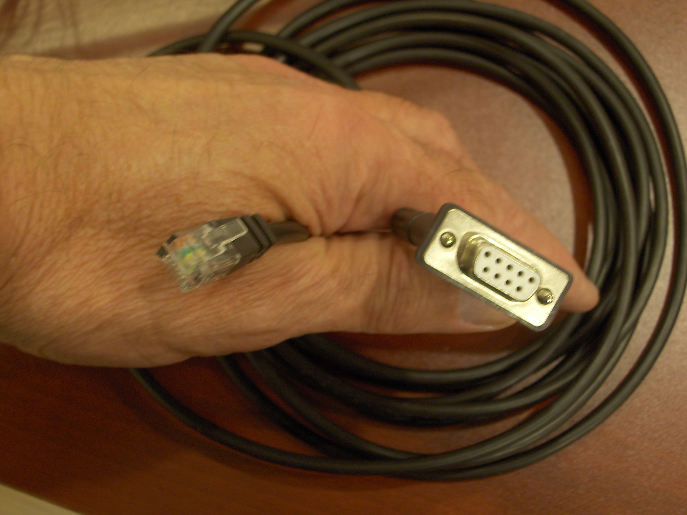
·I've included a picture of the overall system showing the CLICK PLC trainer connected by a serial cable to the Stamp which is mounted on an EnT general purpose i/o board which I designed several years ago and it is the heart of many of my projects. The only additional parts used are the serial cable with a modular plug on one end to fit the PLC and a MAX233 chip to convert the Stamp serial levels to those expected by the PLC.
· This communication allows easy expansion of the i/o for a Stamp, or can give the PLC some extra processing power not usually available in small PLC's.
· Then, I thought that if it works with a cable, maybe having it work wirelessly would be kind of interesting to try as well.
· I had·a set of XBee 1 mW modules and also had a set of SparKFun breakout boards for the XBee's. There are many variations of breakout boards around and all I can say is that the extra $10 is well worth it. They do the level shifting from 3.3 v to 5 v, they accomodate the tiny spacing of the XBee pins and they also provide some indicator LEDs which make troubleshooting easier by showing data in, data out and also RSSI and Power ON. On mine, I soldered a 4-pin header on one end so the board can plug directly into a breadboard.
·· What I wanted was the ability to unplug the serial cable, plug in the XBee's and have the system function with a minmum of fiddling around with XBee settings. So, each XBee got a MAX233 chip to make all serial signals "real" as opposed to the ttl levels normally spoken by XBee's.
··
·· In looking for an easy way to set the XBee comm parameters (1200/8/N/1 in this case), I loaded the free X-CTU utility from Digi/Maxstream on my laptop and in a short time had clicked my way through the changes. In using X-CTU, just keep reminding yourself that two menus are used: the one labeled "PC Settings" sets the laptop serial port settings and the tab labeled "Modem Configuration" is the XBee settings. They have to match in order to talk to your XBee module over the standard serial cable. Click on "Read" and it will retrieve the current settings, make any changes (like baud rate), then click "Write" to update the XBee.
· Adding a couple of 9-pin connectors to the XBee/Max233 setups allowed plugging in to the Stamp on one side and the PLC on the other.
··Powered on and lights started blinking on both ends to confirm the two-way conversation.
· Haven't tried for maximum distance yet, but with one unit in the basement and the other at the opposite end of the house upstairs, everything keeps on ticking along.
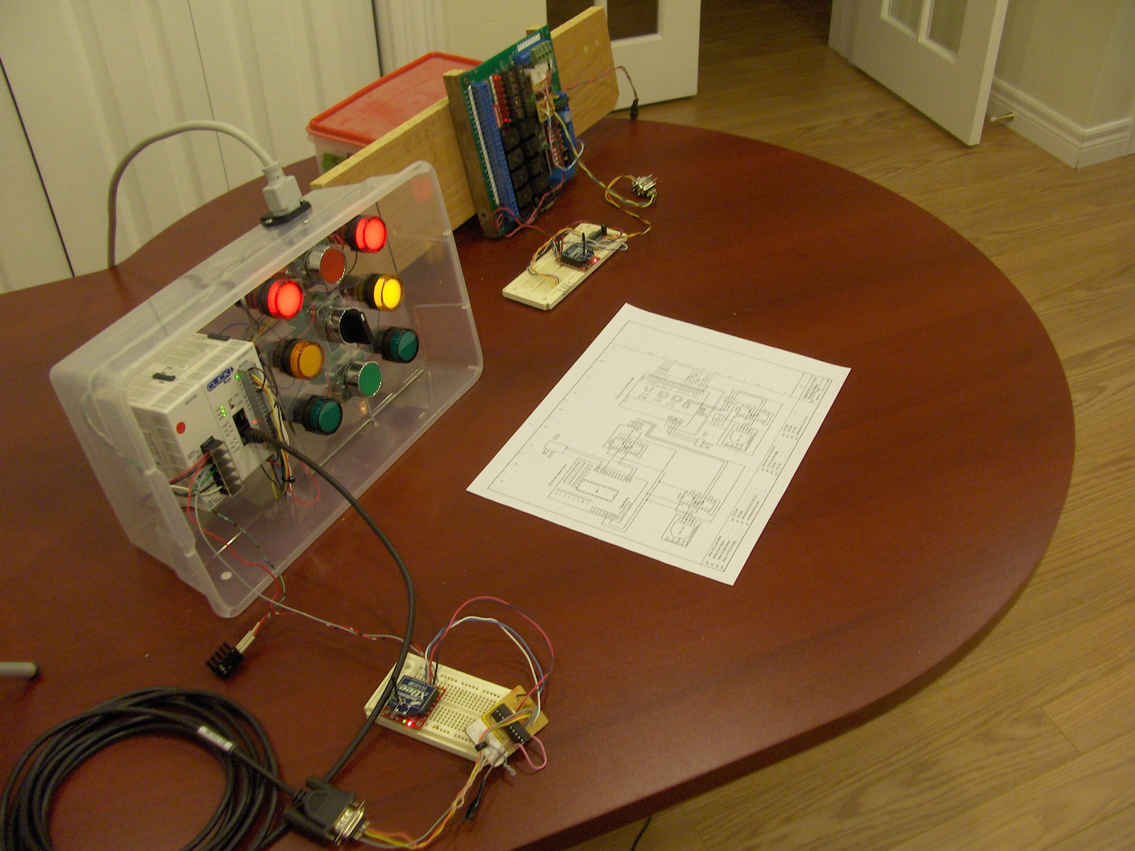
· More pics show the setup running with the XBee's and I've included the connection diagrams as well for both configurations.
· Happy to answer any questions.
· http://www.youtube.com/watch?v=_0tLGrKDyBI···· ---added Mar 11/10
· Cheers,
·
▔▔▔▔▔▔▔▔▔▔▔▔▔▔▔▔▔▔▔▔▔▔▔▔
Tom Sisk
http://www.siskconsult.com
Post Edited (stamptrol) : 6/25/2010 5:22:55 PM GMT


Comments
▔▔▔▔▔▔▔▔▔▔▔▔▔▔▔▔▔▔▔▔▔▔▔▔
Tom Sisk
http://www.siskconsult.com
Looks lke programming is through a serial interface , is it possible to do on line edits wirelessly , maybe even have a network of PLC's with on line editing enabled.
Jeff T.
The programming of the PLC is indeed via serial port 1 but I don't think this little guy ( at $69) is set up to deal with the latency of the the wireless link. Also, at this level of PLC, the editing can be done while the process runs, but the download takes it off-line for several seconds. But, its worth a try. I'll report in once I get a chance to try it. There is a small HMI that works off the port, so it just might respond with a wireless link. From what I remember of the Dataliner, it should work.
I also want to use the XBee's with Quicktrol that we worked on a while ago.
Now that the building blocks are in place, there are lots of possibilities.
Cheers,
▔▔▔▔▔▔▔▔▔▔▔▔▔▔▔▔▔▔▔▔▔▔▔▔
Tom Sisk
http://www.siskconsult.com
Post Edited (stamptrol) : 3/11/2010 2:23:11 PM GMT
· http://www.youtube.com/watch?v=JvG6TBVrh8c
·
▔▔▔▔▔▔▔▔▔▔▔▔▔▔▔▔▔▔▔▔▔▔▔▔
Tom Sisk
http://www.siskconsult.com
·
First time I've seen the XBee in use and that's prodded some thoughts.
DJ
▔▔▔▔▔▔▔▔▔▔▔▔▔▔▔▔▔▔▔▔▔▔▔▔
I want to ask to you, how to connect XBee to PLC?
Which PLC do you want to use and what connectivity do you need? (program wirelessly, data, or both).
Cheers,
Can you explain to me? If you have the program, please upload.
Thank you.
Please let me know what specifically you need.
Thanks..