

DS1307 with Prop and RTCEngineDS1307
 Amaral
Posts: 176
Amaral
Posts: 176
Hello all !
I’m having an odd behave on my DS1307 (RTC) chip with this object “RTCEngineDS1307”, the clock is really slow, missing time like 8 minutes per hour! The thing is that the same chip running on a BS2Pe, in the same breadboard works perfectly. The object is very clear and well made, at first I could not believe that there was something wrong with that, but now I don’t know anymore what to think, if it’s me that is making some stupid mistake or anything else !
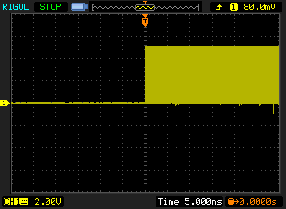
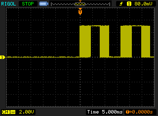
I took some measurements on an oscilloscope on the SWQ/OUT pin of the DS1307 with the same frequency set to be out (8.192 kHz), and this show an even more odd behavior, with the BS2Pe the wave is continuous (as it should be) but on the propeller driven DS1307 the wave is broken from time to time (see images attached )
I’m really missing something here, if anyone can help me would be very appreciable.
I attached the object and the codes of both too, just for clarity .
Thanks in advance.
Amaral.
I’m having an odd behave on my DS1307 (RTC) chip with this object “RTCEngineDS1307”, the clock is really slow, missing time like 8 minutes per hour! The thing is that the same chip running on a BS2Pe, in the same breadboard works perfectly. The object is very clear and well made, at first I could not believe that there was something wrong with that, but now I don’t know anymore what to think, if it’s me that is making some stupid mistake or anything else !
I took some measurements on an oscilloscope on the SWQ/OUT pin of the DS1307 with the same frequency set to be out (8.192 kHz), and this show an even more odd behavior, with the BS2Pe the wave is continuous (as it should be) but on the propeller driven DS1307 the wave is broken from time to time (see images attached )
I’m really missing something here, if anyone can help me would be very appreciable.
I attached the object and the codes of both too, just for clarity .
Thanks in advance.
Amaral.

Comments
BTW, I'm guessing that your timing or clock frequency of the Prop is incorrect somewhere.
▔▔▔▔▔▔▔▔▔▔▔▔▔▔▔▔▔▔▔▔▔▔▔▔
*Peter*
Post Edited (Peter Jakacki) : 3/8/2010 12:50:13 AM GMT
The reason I say this is that you can still see the clock output riding on the high or low of the 100Hz.
▔▔▔▔▔▔▔▔▔▔▔▔▔▔▔▔▔▔▔▔▔▔▔▔
*Peter*
Ok, I just checked the driver and it seems to be setting that bit automatically.
▔▔▔▔▔▔▔▔▔▔▔▔▔▔▔▔▔▔▔▔▔▔▔▔
*Peter*
▔▔▔▔▔▔▔▔▔▔▔▔▔▔▔▔▔▔▔▔▔▔▔▔
*Peter*
PUB setSQWOUTFrequency(frequency) '' 13 Stack Longs
'' ┌──────────────────────────────────────────────────────────────────────────────────────────────────────────────────────────┐
'' │ Turns the square wave on. │
'' │ │
'' │ Frequency - Selects the frequency of the square wave pin. (0 - 1HZ), (1 - 4.096KHZ), (2 - 8.192KHZ), (3 - 32.768KHZ). │
'' └──────────────────────────────────────────────────────────────────────────────────────────────────────────────────────────┘
setRAM(7, ($10 | ((frequency <# 3) #> 0)))
this setRAM on the end gives me the SQWE with this $10 right before the freq. At least that was what I deduced ! but I can be wrong, as I told before, the driver is so clean that I don't believe that is the problem !
*Peter* "
Sorry peter ... but I did not get what you mean !
▔▔▔▔▔▔▔▔▔▔▔▔▔▔▔▔▔▔▔▔▔▔▔▔
*Peter*
Amaral
My goodness, I just realized that is slowed down. That's your problem there, that is 50Hz (or 60Hz) coming in.
▔▔▔▔▔▔▔▔▔▔▔▔▔▔▔▔▔▔▔▔▔▔▔▔
*Peter*
Post Edited (Peter Jakacki) : 3/8/2010 1:31:57 AM GMT
The problem just disappeared !
I reload all the flashing lights and even some parts for controlling the push buttons, and now it’s working normally !
Is there any possibility of the resonator to be with some kind of charge inside, or anything that during the test just discharged or charged, or got rib of ! have you ever heard about anything like that ?
The sad part is that I’ll never know what was happening ! that makes my project not really trustable .
Thank you very much, the sequence of tests made it go back ( and I lost a hole Sunday afternoon on that, but now I know how to test a resonator ) .
If you have any idea of what was happening please share !
Amaral
PS: over here is all 60Hz , but my power supply is very clean!
Desapeared for a moment , and now is back again !
BTW, make sure that you clean the flux off properly from around the RTC. It affects both the oscillator and the standby current.
▔▔▔▔▔▔▔▔▔▔▔▔▔▔▔▔▔▔▔▔▔▔▔▔
*Peter*
ok .. no idea how to get rib of it !
Is your 'scope well-grounded to the circuit? If not, it would be picking up power line hum.
▔▔▔▔▔▔▔▔▔▔▔▔▔▔▔▔▔▔▔▔▔▔▔▔
Tracy Allen
www.emesystems.com
Yeap the pull ups are ok !
I'm using a battery , I have made the mistake of lefting the pin 3 Batt floating before !
The communication is solid and good , I can access NVRAM, I can set time , but I get that funny thing on the pin 7 , and Im running the clock slow !
When I power off the circuit, the occilator stops too, I don't miss data from NVRAM and I don't get the clock (RTC) zeroed, but the seconds does not advance ! Still with the BS2p . everything works perfect , with all the combinations of DS1307 and cristals that I have ( I have two DS1307 and four Cristals, not welded anymore).
Another interesting thing, when I power up , it takes around 10 seconds to start changing the seconds ! It's becamming clear that is a hardware problem, but I still cannot isolate it !
Any suggestions are welcome !
Amaral
▔▔▔▔▔▔▔▔▔▔▔▔▔▔▔▔▔▔▔▔▔▔▔▔
*Peter*
Tomorow I´ll re assembly everything and see if it makes any difference ..
·
So, I would say that you definately have a hardware problem with your setup. Check to make sure you put a by pass capacitor on the 5V rail near it. Ive had many problems before with devices when the bypass cap was left out.
▔▔▔▔▔▔▔▔▔▔▔▔▔▔▔▔▔▔▔▔▔▔▔▔
Nyamekye,
▔▔▔▔▔▔▔▔▔▔▔▔▔▔▔▔▔▔▔▔▔▔▔▔
My Prop Info&Apps: ·http://www.rayslogic.com/propeller/propeller.htm
My Prop Products:· http://www.rayslogic.com/Propeller/Products/Products.htm
I had an emergency at my job and will return just by the end of the week... if I am lucky. but then I'll check everything, including the cap close to the rail. I'll post news as I have it ..
Thanks all
Thanks for the help !
Protoboard. There's your fix.
▔▔▔▔▔▔▔▔▔▔▔▔▔▔▔▔▔▔▔▔▔▔▔▔
Nyamekye,