

Servo Shield for Prop Platform - going to production 3/26/2010
 Brian Riley
Posts: 626
Brian Riley
Posts: 626
I have been thinking about a bunch of things with regard to the PRC (Propeller Robot Controller) that Mark McCann and I developed in the early days of Propeller. It went out as rev 1.02 and there was an upgrade to rev 2.0. There were flaws in 2.0 all which could be soundly remedied.
Enter JonnyMac's "Propeller Platform" that has been so ably put into production and being further enhanced by Gadget Gangster .. this has made my thinking easier. I really like the PropPlatform form factor. BY making it using Express PCB's 3.8x2.5 factor it means anyone can run off a special design for a shield and get it to copper for a reasonable amount. I am not going to update the PRC and instead throw my support to GG's Prop Platform.
The PRC is not dead, he is rising from his own ashes, as a shield for the Prop Platform. None of he PP shields to date address multiple servo's. Sooooooooooooo ....
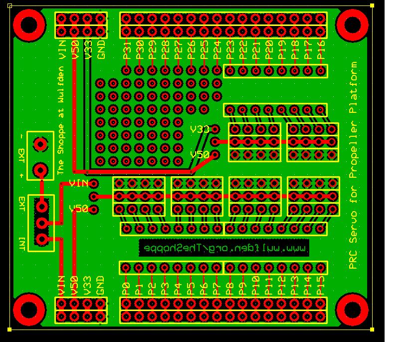
Enter the "PRC Servo for the Propeller Platform," a Propeller Platform based controller with 24 standard 3 pin connectors (GND, V+, SIG). The board is 2.8" by 2.5", all servo connecters have holes for jumper or series resistors.P0-P15 have a jumper selection for Vin or 5v, P16-P23 have jumper selection for 5V or 3.3V. P24-P31 is accessible with a small prototyping area.
The Vin power to P0-P15 is switch selectable between PropPlatform buss Vin and an external terminal block.
I am posting this now because I plan to put in for a proto board run on Tuesday, and I wanted to see what you guys thought and what I missed.
cheers ... BBR
3/10/2010 - The board, pretty much as shown in the fourth (last) picture is into ExpressPCB for prototyping. I expect to have it Friday 3/12.
3/13/2010 - prototype boards received - looks good ... see new entry below
3/25/2010 - board checks out - with minor tweaks going to production tomorrow - see my message on 3/25/2010 for final layout
▔▔▔▔▔▔▔▔▔▔▔▔▔▔▔▔▔▔▔▔▔▔▔▔
cheers ... brian riley, n1bq, underhill center, vermont
The Shoppe at Wulfden
www.wulfden.org/TheShoppe/
Post Edited (Brian Riley) : 3/25/2010 11:47:30 PM GMT
Enter JonnyMac's "Propeller Platform" that has been so ably put into production and being further enhanced by Gadget Gangster .. this has made my thinking easier. I really like the PropPlatform form factor. BY making it using Express PCB's 3.8x2.5 factor it means anyone can run off a special design for a shield and get it to copper for a reasonable amount. I am not going to update the PRC and instead throw my support to GG's Prop Platform.
The PRC is not dead, he is rising from his own ashes, as a shield for the Prop Platform. None of he PP shields to date address multiple servo's. Sooooooooooooo ....
Enter the "PRC Servo for the Propeller Platform," a Propeller Platform based controller with 24 standard 3 pin connectors (GND, V+, SIG). The board is 2.8" by 2.5", all servo connecters have holes for jumper or series resistors.P0-P15 have a jumper selection for Vin or 5v, P16-P23 have jumper selection for 5V or 3.3V. P24-P31 is accessible with a small prototyping area.
The Vin power to P0-P15 is switch selectable between PropPlatform buss Vin and an external terminal block.
I am posting this now because I plan to put in for a proto board run on Tuesday, and I wanted to see what you guys thought and what I missed.
cheers ... BBR
3/10/2010 - The board, pretty much as shown in the fourth (last) picture is into ExpressPCB for prototyping. I expect to have it Friday 3/12.
3/13/2010 - prototype boards received - looks good ... see new entry below
3/25/2010 - board checks out - with minor tweaks going to production tomorrow - see my message on 3/25/2010 for final layout
▔▔▔▔▔▔▔▔▔▔▔▔▔▔▔▔▔▔▔▔▔▔▔▔
cheers ... brian riley, n1bq, underhill center, vermont
The Shoppe at Wulfden
www.wulfden.org/TheShoppe/
Post Edited (Brian Riley) : 3/25/2010 11:47:30 PM GMT
840 x 685 - 175K
Comments
Nice Board - BUT.
In my opinion need some Caps and LF to to be correct
Regards
▔▔▔▔▔▔▔▔▔▔▔▔▔▔▔▔▔▔▔▔▔▔▔▔
Nothing is impossible, there are only different degrees of difficulty.
For every stupid question there is at least one intelligent answer.
Don't guess - ask instead.
If you don't ask you won't know.
If your gonna construct something, make it·as simple as·possible yet as versatile as posible.
Sapieha
I was thinking about two big (220-1000 uF) caps one on each power line to the two groups (P0-P15 and P16-P23). Anywhere else?
"LF" ?????
Thanks for the suggestions.
cheers ... BBR
▔▔▔▔▔▔▔▔▔▔▔▔▔▔▔▔▔▔▔▔▔▔▔▔
cheers ... brian riley, n1bq, underhill center, vermont
The Shoppe at Wulfden
www.wulfden.org/TheShoppe/
It looks like the servos can be powered from the VR on the Prop Platform or via an external power supply, so that's good. I would make the power traces wider. Running multiple servos can draw a lot of power and might burn out thinner traces.
I don't know what LF is, but caps are good.
I also put up the specifications for Propeller Platform modules here, although it looks good to me as-is, you might want to check the mounting hole spacing.
▔▔▔▔▔▔▔▔▔▔▔▔▔▔▔▔▔▔▔▔▔▔▔▔
Propeller Forums RSS Feed!
Gadget Gangster - Share your Electronic Projects
Since you could be running a lot of servos I suggest you put a 100-ohm resistor inline with the control outputs, with a 0.001uF to ground -- this will keep noise from the servos from getting back to the Propeller (I'm doing this on a future N&V project board). I also agree with adding a couple big ol' caps on the power rails to the servo headers (I did this on the DMX board with servo headers).
▔▔▔▔▔▔▔▔▔▔▔▔▔▔▔▔▔▔▔▔▔▔▔▔
Jon McPhalen
Hollywood, CA
@Nick - The power traces are what I had on my PRC, I will see about going up a bit. I started with the PP ExpressPCB file and removed everything extraneous and locked down what was left. When I trimmed to 2.8 from 3.8 I made sure the mounting holes were 0.15 from each edge.
@JonnyMac - I have a space to either be jumpered or place a resistor for each line P0 to P23. Which side of the resistor would you put a .001 cap? prop side or servo side
duh ... .001 is that a "102" ????
cheers ... BBR
▔▔▔▔▔▔▔▔▔▔▔▔▔▔▔▔▔▔▔▔▔▔▔▔
cheers ... brian riley, n1bq, underhill center, vermont
The Shoppe at Wulfden
www.wulfden.org/TheShoppe/
▔▔▔▔▔▔▔▔▔▔▔▔▔▔▔▔▔▔▔▔▔▔▔▔
Jon McPhalen
Hollywood, CA
1 - added two big electrolytics, one on each chain. I am thinking 1000 uF on the main and 470 uF on the secondary. They are gonna have to stand up, but then the servo connectors will be up tall as well.
2 - increased the high power traces from .030" to .050"
3 - made left hand column of holes in proto area with 2 x 5v, 2 x 3.3v and 3 x Gnd connections
JonnyMac suggests .001 uF caps from signal to ground on servo side of series resistors ..... I am gonna have to think on that. How to cleanly put them in.
Does anyone have any comments or thoughts on my selection of Vin and 5V for P0-P15 and 5V and 3.3V for P16-P23 ??????
cheers ... BBR
▔▔▔▔▔▔▔▔▔▔▔▔▔▔▔▔▔▔▔▔▔▔▔▔
cheers ... brian riley, n1bq, underhill center, vermont
The Shoppe at Wulfden
www.wulfden.org/TheShoppe/
though the new SD version is a shortboard http://www.gadgetgangster.com/find-a-project/56?projectnum=281
pcbexpress mini board service only come in one size anyway.
Post Edited (tonyp12) : 3/8/2010 3:11:17 AM GMT
If it is successful I plan to produce this board for sale, but I will post the ExpressPCB ".pcb" file for anyone to use.
p.s. yes, mini-board service is limited to 3.8 x 2.5 ... but there is a miraculous group of tools, the ruler, the straight edge, the fine marker, and the hacksaw ... poof ... 3.8 inches becomes 2.8 inches! I added another tool ... a Ryobi 9" benchtop bandsaw ... the aforementioned transformation will take 5 minutes, start to finish.
cheers ... BBR
▔▔▔▔▔▔▔▔▔▔▔▔▔▔▔▔▔▔▔▔▔▔▔▔
cheers ... brian riley, n1bq, underhill center, vermont
The Shoppe at Wulfden
www.wulfden.org/TheShoppe/
I have done some shortboard modules primarily because of cost - some modules just don't justify the full 3.8x2.5 size. Brian is right - it's quite firmly attached, even without standoffs.
▔▔▔▔▔▔▔▔▔▔▔▔▔▔▔▔▔▔▔▔▔▔▔▔
Propeller Forums RSS Feed!
Gadget Gangster - Share your Electronic Projects
Sorry my bad english.
LF = Ferrite Bed else other type of LC filter.
Ps. see picture
Regards
▔▔▔▔▔▔▔▔▔▔▔▔▔▔▔▔▔▔▔▔▔▔▔▔
Nothing is impossible, there are only different degrees of difficulty.
For every stupid question there is at least one intelligent answer.
Don't guess - ask instead.
If you don't ask you won't know.
If your gonna construct something, make it·as simple as·possible yet as versatile as posible.
Sapieha
Its my idea that 95% of servo projects would be using 16 or less servos in bank 1 (P0-P15) and the second bank (P16-P23) would be sensors, many of which use the familiar 3 pin cable.
Cheers ... BBR
▔▔▔▔▔▔▔▔▔▔▔▔▔▔▔▔▔▔▔▔▔▔▔▔
cheers ... brian riley, n1bq, underhill center, vermont
The Shoppe at Wulfden
www.wulfden.org/TheShoppe/
I did a lot of thinking about what I said here while munching on my lunch. I had these thoughts.
1 - most robots use 2-6 servo's, many only 3 (2 wheels and maybe a Ping). Lynx Motion HexaCrawlers and their ilk being the exception.
2 - grouping them 16 and 8 means that to chose heavier (7.2v NiMH say) power dooms sixteen I/O pins to high power
3 - many robots today use many sensors, (more than 8)
So ... here is what I did:
I split P0 to P15 into two banks. Now we have Bank 0 (P0-P7), Bank 1 (P8-P15), and Bank 2 (P16-P23)
----> Bank 0, as before, is fed by, jumper selectable, Vin or 5V
----> Bank 2, as before, can be fed by, jumper selectable, 5V or 3.3V
----> Bank 1 can be fed by, jumper selectable, whatever feeds Bank 0 or whatever feeds Bank 2
... OR ... leave out the 3 pin headers for the jumpers and use heavy wire to hand make the jumpers and you could easily have the Banks be whatever you want them to be ... say, Bank 0 be Vin, Bank 1 be 5V and Bank 2 be 3.3V .....
@Jonny Mac, there is no room to cleanly put the .001 caps on. The only solution I see is use Kemet monolithics with short leads and 0.2" lead spacing placing them on the bottom across the 3 pin connectors - see my next message.
cheers ... BBR
▔▔▔▔▔▔▔▔▔▔▔▔▔▔▔▔▔▔▔▔▔▔▔▔
cheers ... brian riley, n1bq, underhill center, vermont
The Shoppe at Wulfden
www.wulfden.org/TheShoppe/
Post Edited (Brian Riley) : 3/8/2010 11:39:58 PM GMT
John Abshier
@JonnyMac - I got your caps in for Banks 0 & 1 - I generally supply 1/8th watt carbon film resistors with my kits so I am pretty sure we can get the R and the C squeezed in there.
I was also able to boost the high power traces to .060" without any crowding
Does anyone see anything wrong? ... or that could be better? In the absence of any further change, I plan to submit it for a mini-board run for tomorrow's deadline. That should get them back to me for the weekend.
cheers ... BBR
▔▔▔▔▔▔▔▔▔▔▔▔▔▔▔▔▔▔▔▔▔▔▔▔
cheers ... brian riley, n1bq, underhill center, vermont
The Shoppe at Wulfden
www.wulfden.org/TheShoppe/
I liked the pervious version in that you could stick a resistor pack in line with the signal line, (looks like .3 spacing). I like to use resistor packs on my servo projects, cover 8 outputs at once.
My .02,
Jim
It is 0.3" spacing and you can still do it ... just forego the .001 uƒ·caps and put the resistor pack in place.
cheers ... BBR
▔▔▔▔▔▔▔▔▔▔▔▔▔▔▔▔▔▔▔▔▔▔▔▔
cheers ... brian riley, n1bq, underhill center, vermont
The Shoppe at Wulfden
www.wulfden.org/TheShoppe/
Should have looked a little closer. Very cool!
Jim
cheers ... BBR
▔▔▔▔▔▔▔▔▔▔▔▔▔▔▔▔▔▔▔▔▔▔▔▔
cheers ... brian riley, n1bq, underhill center, vermont
The Shoppe at Wulfden
www.wulfden.org/TheShoppe/
Visual inspection
- no obvious stupidities
- mounting and connector holes line up perfectly with PP long board and PPSD short board I just got from Nick
Mechanical inspection
- I have recorded five small problems in hole sizes and placements all of which can be worked around on this board ... fixes involve tweaking, not re-designing!
- the RC filter circuit in Banks 0 and 1 worked out fine, assembly is a beast, tedious though, not tricky.
Electrical checkout
- everything works as intended
I plan another few days shakedown with 8 servos and a bunch sensors and an serial LCD display.
cheers ... BBR
▔▔▔▔▔▔▔▔▔▔▔▔▔▔▔▔▔▔▔▔▔▔▔▔
cheers ... brian riley, n1bq, underhill center, vermont
The Shoppe at Wulfden
www.wulfden.org/TheShoppe/
- rearranged 5,v, 3.3v and GND pads in small proto area
- added opposite side traces for the heavy power buss effectively doubling the current capacity - more important reducing I2R losses
- fixed a half dozen minor hole alignments.
- settled on "PRC4PP" as formal name meaning "Propeller Robot Controller for Propeller Platform"
- expect to have boards available in 3 weeks
Its important to remember this layout and connectors can do more than just servo's, 2/3rds of Parallax's sensors and other dohickeys connect via a three pin interface.
Tentatively, a bare PCB will be $12 and there will be two levels of parts kits a bare bones with non optional parts and connector and resistors and caps for 8 ports and a 'soup-to-nuts' kit. I haven't figure kit prices yet.
cheers ... BBR
▔▔▔▔▔▔▔▔▔▔▔▔▔▔▔▔▔▔▔▔▔▔▔▔
cheers ... brian riley, n1bq, underhill center, vermont
The Shoppe at Wulfden
www.wulfden.org/TheShoppe/