

DIY Circuit board drilling service
 metron9
Posts: 1,100
metron9
Posts: 1,100
I am making circuit boards now up to 10 x 10 with my new CNC router.
I am thinking of offering a service for single side boards.
Looking at some of the posts of those of you doing your own photo etch boards, I came up with a thought
of supplying drilled boards to your design spec that you could then photo etch (after drilling).
Pre drilled .100 spaced holes may also be an option if traces you make allow for the holes on a grid pattern.
I don't know if you start with copper boards, then add the photo etch or if you use pre sensitized boards.
I have a supplier that does military spec boards, I have .062 and .031 FR4 (matt green finish) on order.
Who want's to get started either doing your own or perhaps a joint effort I drill you etch service.
I have a process to do G-Code using eagle gerber files created with eagle.
I use several programs to get the outlines I need as well as the drill files.
At the moment my machine holds .0005 (best I can tell) using a think and tinker bit I mill .010 deep
What I use in eagle is .047 track width and .050 centers. That leaves .003 between traces. those traces get milled creating a .020 gap so you end up with a .037 trace width.
This is not the smallest but it is great for simple designs. I will post some pictures of the work I am doing tonight.
Last night I did a 6 x 6 inch board that took 7 min for 220 holes and that is about 1/2 speed, (I have not cranked it up to break drill point yet to find the maximum speed)
I am typically running at 150 IPM rapids and i can run at 320.
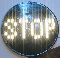
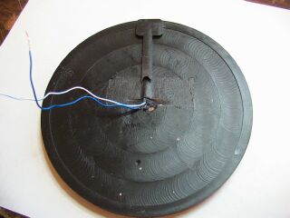
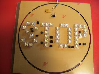
Pictures uploaded, this is a stop light for a guy that has an old school buss STOP sign made of glass. He is going to use it on his bike as the taillight above the existing running and break lights. It will only go on when pressing the break.
I made a mold of wax and used epoxy potting compound to embed the circuit board and led's.
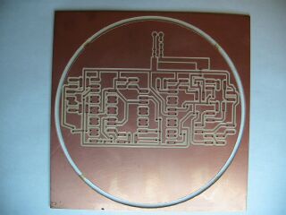
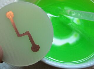
The picture of the round PCB is my first try at using 2 parts Hydrogen peroxide and 1 part muriatic acid, i used a sharpie to draw the circuit line.
I am going to try using our UV activated liquid film that we use to make silk screen images on screens by screen printing it on some circuit boards. If it works i may be able to drill the boards first, then expose the board in a vacuum table and UV light to get very fine traces. I can make the negative on my indigo press. Since the holes can be predrilled it will be easy to lay up the negative excatly on the holes for double sided boards as well.
▔▔▔▔▔▔▔▔▔▔▔▔▔▔▔▔▔▔▔▔▔▔▔▔
Think Inside the box first and if that doesn't work..
Re-arrange what's inside the box then...
Think outside the BOX!
Post Edited (metron9) : 3/7/2010 3:25:39 AM GMT
I am thinking of offering a service for single side boards.
Looking at some of the posts of those of you doing your own photo etch boards, I came up with a thought
of supplying drilled boards to your design spec that you could then photo etch (after drilling).
Pre drilled .100 spaced holes may also be an option if traces you make allow for the holes on a grid pattern.
I don't know if you start with copper boards, then add the photo etch or if you use pre sensitized boards.
I have a supplier that does military spec boards, I have .062 and .031 FR4 (matt green finish) on order.
Who want's to get started either doing your own or perhaps a joint effort I drill you etch service.
I have a process to do G-Code using eagle gerber files created with eagle.
I use several programs to get the outlines I need as well as the drill files.
At the moment my machine holds .0005 (best I can tell) using a think and tinker bit I mill .010 deep
What I use in eagle is .047 track width and .050 centers. That leaves .003 between traces. those traces get milled creating a .020 gap so you end up with a .037 trace width.
This is not the smallest but it is great for simple designs. I will post some pictures of the work I am doing tonight.
Last night I did a 6 x 6 inch board that took 7 min for 220 holes and that is about 1/2 speed, (I have not cranked it up to break drill point yet to find the maximum speed)
I am typically running at 150 IPM rapids and i can run at 320.
Pictures uploaded, this is a stop light for a guy that has an old school buss STOP sign made of glass. He is going to use it on his bike as the taillight above the existing running and break lights. It will only go on when pressing the break.
I made a mold of wax and used epoxy potting compound to embed the circuit board and led's.
The picture of the round PCB is my first try at using 2 parts Hydrogen peroxide and 1 part muriatic acid, i used a sharpie to draw the circuit line.
I am going to try using our UV activated liquid film that we use to make silk screen images on screens by screen printing it on some circuit boards. If it works i may be able to drill the boards first, then expose the board in a vacuum table and UV light to get very fine traces. I can make the negative on my indigo press. Since the holes can be predrilled it will be easy to lay up the negative excatly on the holes for double sided boards as well.
▔▔▔▔▔▔▔▔▔▔▔▔▔▔▔▔▔▔▔▔▔▔▔▔
Think Inside the box first and if that doesn't work..
Re-arrange what's inside the box then...
Think outside the BOX!
Post Edited (metron9) : 3/7/2010 3:25:39 AM GMT
247 x 240 - 41K
320 x 240 - 17K
320 x 240 - 20K
320 x 240 - 19K
320 x 236 - 28K