

two photoelectric sensor one relay
 Gaber
Posts: 12
Gaber
Posts: 12
I'm always trying to keep myself busy and now I am stuck in this wiring !!
I bought averything I needed for my project (two sensors, a 24VDC relay, power supply amd of course , the Solenoid valve)
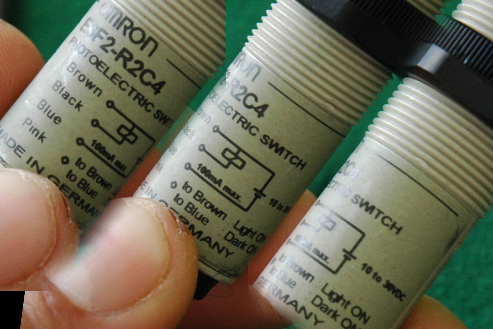
I am using two omron E3F2-R2C4 photoelectric switch sensors
the plan is,
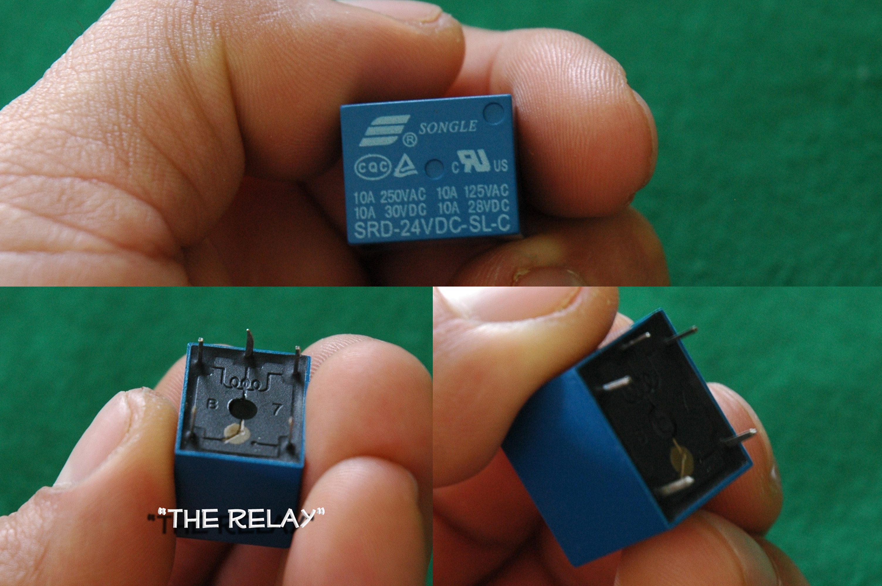
The Relay will keep the Voltage applied to the Solenoid valve when the object is detected.
Then the second sensor will trigger when the (Pneumatic Cylinder) is fully extracted and turn off the Relay and this will retract the Piston.
I got a 24DC power supply to power the solenoid and the sensors.
This is a single acting Open/Close solenoid valve. When voltage is applied, it will extract the Piston and when voltage is removed the piston will retract.
any comment/help will be appreciate it.
Gabe
I bought averything I needed for my project (two sensors, a 24VDC relay, power supply amd of course , the Solenoid valve)
I am using two omron E3F2-R2C4 photoelectric switch sensors
the plan is,
The Relay will keep the Voltage applied to the Solenoid valve when the object is detected.
Then the second sensor will trigger when the (Pneumatic Cylinder) is fully extracted and turn off the Relay and this will retract the Piston.
I got a 24DC power supply to power the solenoid and the sensors.
This is a single acting Open/Close solenoid valve. When voltage is applied, it will extract the Piston and when voltage is removed the piston will retract.
any comment/help will be appreciate it.
Gabe
3008 x 2000 - 1M
1597 x 1065 - 354K
1698 x 1132 - 529K
Comments
▔▔▔▔▔▔▔▔▔▔▔▔▔▔▔▔▔▔▔▔▔▔▔▔
- Stephen
the big question is , How can I wire everything so that one sensor turns the relay on and the other sensor turns it off.
Thanks for the comment STEPHEN.
By the way I already tried one sensor and It did work and turned the solenoid valve now I dont know how can I hook the other one up.
Post Edited (Gaber) : 3/3/2010 11:17:31 PM GMT
If you are using the pneumatic cylinder to move the detected object then you will need a flip-flop to be turned on by the detection of the object, and off when the cylinder is fully extended. I would suggest using a 555 timer for that.
Thanks a lot Kwinn.
-Gabe
Post Edited (Gaber) : 3/3/2010 11:23:30 PM GMT
the cylinder pushes the detected object away from the first sensor when activated, and
the second sensor detects the target when the cylinder is fully extended.
thanks Kwinn,
Gabe
tWO MORE QUESTIONS.
When the object reaches the second sensor does it stay there or is it removed before the cylinder retracts and another object is placed in front of the first sensor ?
Can you tell me how much current the relay coil and solenoid coil draw or what their resistance is ?
Post Edited (kwinn) : 3/4/2010 3:46:14 AM GMT
just give a little bit of time.
sorry for the delay.
I think the relay resistance is 1600 let me double check
The object is remove after the cylinder retracts and another object is placed to start the cycle again (there is no timing cycle)
the cycle begins when the object is place in front of the first sensor and ends when the second sensor detects the cylinder's plunger.
The relay coil: Nominal current is 15mA and the coil resistance is 1600 ohm +/- 10%.
The Solenoid Valve :
Flow (at 6 bar, ΔP=1bar) : 1.8 W : (0.1 Cv), 5.4 W : (0.15 Cv)
Voltage range : -15% to +10% of nominal voltage
Power : ∼ Inrush : 10.9 VA
Holding : 7.7 VA
= 1.8 to 12.7 W
Response times : 24 VDC (5.4 W) Energize : 6 ms De-energize : 2 ms
120/60 Energize : 3-8 ms De-energize : 2-7 ms
I'll be working over the weekend with the circuit you gave sir.
one question (since I am not a PRO)
there are three relays right ?
have a good weekend.
I appreciated all your help Sir, its nice to have people like you man,
have a nice weekend.
When I worked on my project this weekend, based on the circuit you gave me, everything worked just fine using a light bulb instead of the solenoid valve, but when I hooked up the solenoid valve nothing happens
you thing that the solenoid valve is not a 24 VDC (the site from where I bought it says "24 VDC") ... Something is wrong man.
this is the pic from the valve, hopefully you can help me again.
I am very thankful for the circuit you gave me it worked pretty good.
Gabe
Here is the schematic. Again, be very careful when working with 120VAC.
MAKE SURE YOU HAVE A FUSE IN THE LINE IN CASE YOU HAVE A SHORT SOMEWHERE.
Post Edited (kwinn) : 3/7/2010 2:55:54 PM GMT
▔▔▔▔▔▔▔▔▔▔▔▔▔▔▔▔▔▔▔▔▔▔▔▔
- Stephen
Post Edited (kwinn) : 3/8/2010 4:54:45 PM GMT
by the way I added the 4th relay to activate the AC solenoid and everything went well.
I will post the progress somtime later, stephen.
Thanks for follow this show.
I do want to tell you that I moved a wire to get what I wanted.
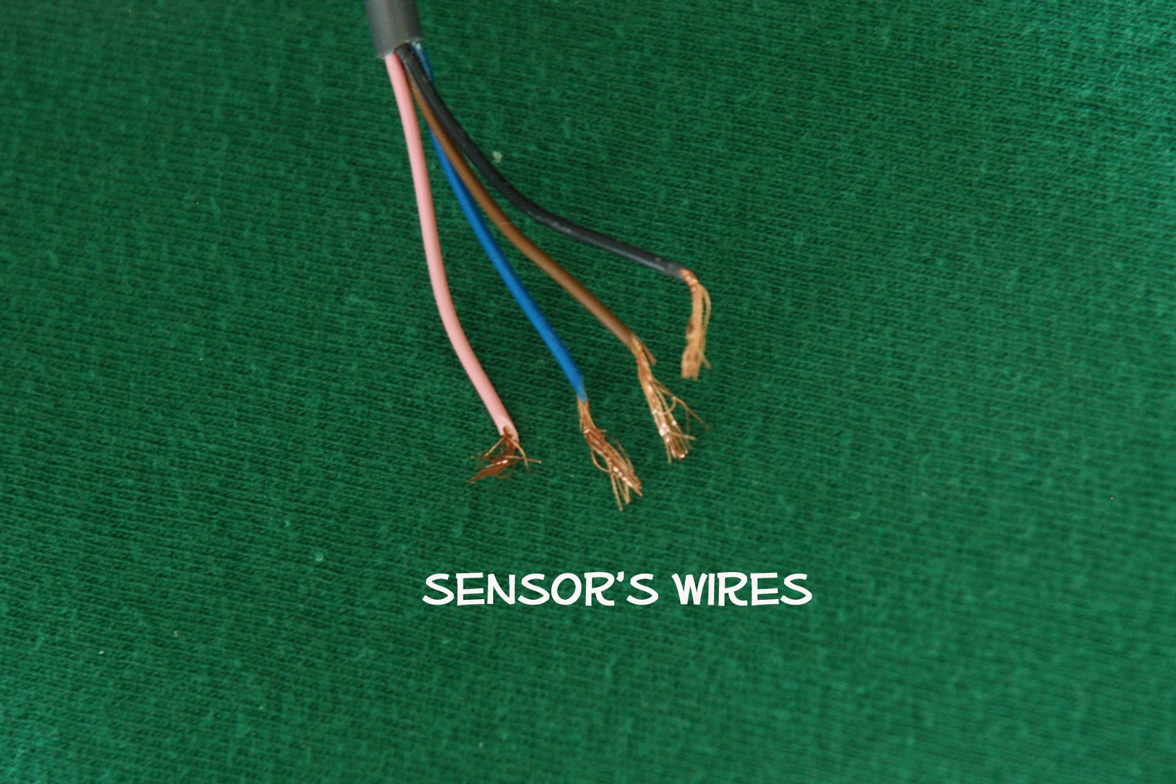
I connected one of the pink wires from the sensors to the brown and the other one stayed with the blue, see the problem was that
the "target" was blocking the two sensor at the same time (sensors were about 5" apart from each other), doing this let me place the "target" in front of the sensors(that was the only way to activate the valve). then when the second sensor doesn't detect the plunger, turns the valve off sending it back to its home position, and the cycle will start by placing the target in fornt of the two sensors @ the same time.
if you dont understand what I said blame it on my English... I am originally from Mexico.
Recylce if you can !!
Post Edited (Gaber) : 3/10/2010 5:13:46 AM GMT