Shop OBEX P1 Docs P2 Docs Learn Events
2V Overshoot on breadboard setup. Is this 'normal'? — Parallax Forums

2V Overshoot on breadboard setup. Is this 'normal'?

grahamreitzgrahamreitz Posts: 56
edited 2010-03-02 17:20 in Propeller 1
_clkmode = xtal1 + pll16x
_xinfreq = 6_250_000

PUB Main
  coginit(0, @main_entry, 3)       

DAT
                        org     0
main_entry        mov     dira, pin
:loop                 xor     outa, pin
                        jmp     #:loop

pin     long        |< 28


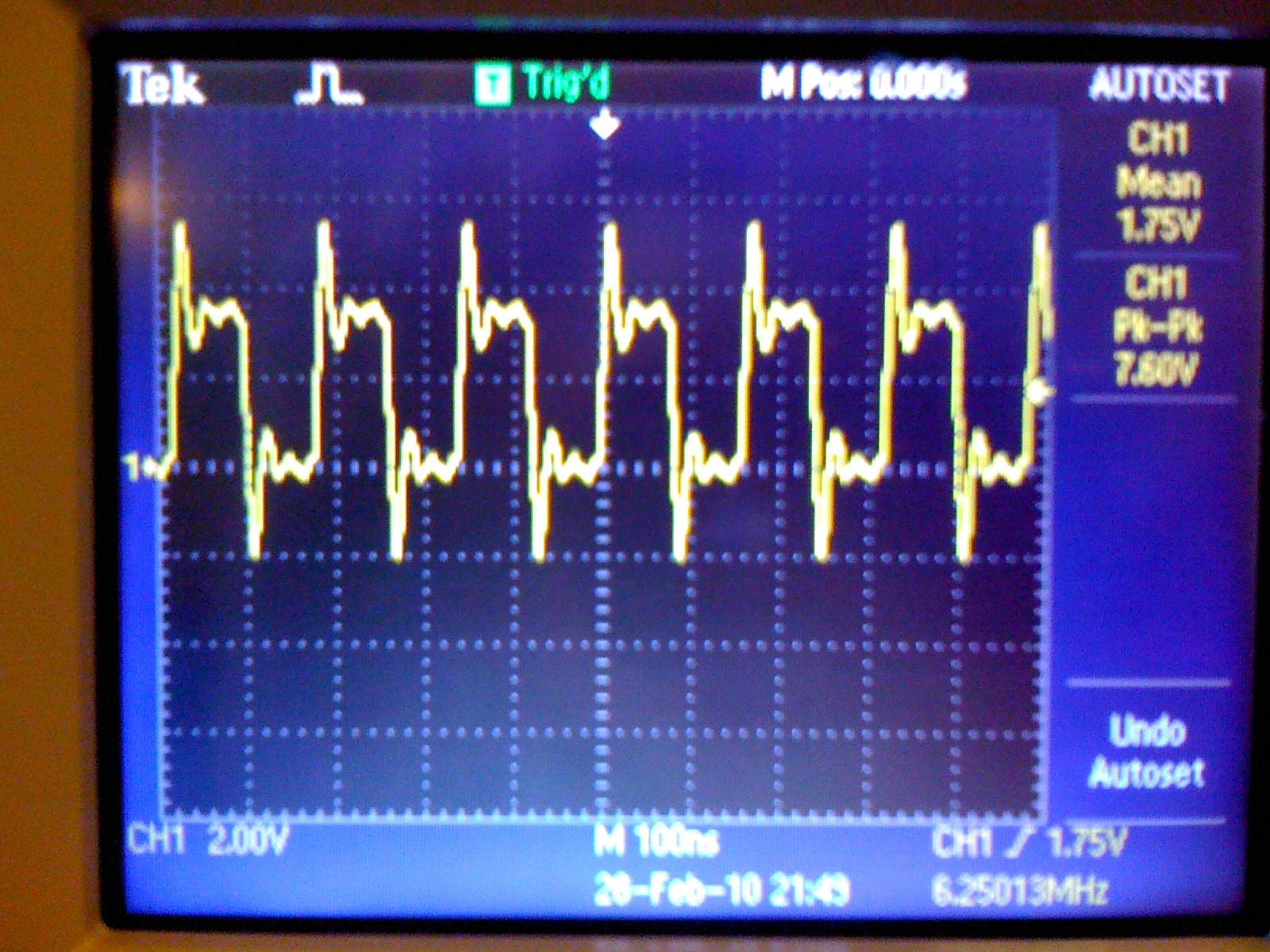
This is a breadboarded prop with a 6.25MHz crystal (my first breadboard prop setup)

The overshoot on the oscilloscope seems excessive @2V (see image). Although, it could easily be my setup.

It does the same thing with the standard 5.00MHz crystal and a different prop chip.

Is acceptable or is there a method to tease out where this may be coming from?

Thanks,
graham

Post Edited (greitz) : 3/1/2010 4:20:46 AM GMT
1600 x 1200 - 330K
«1

Comments

  • Peter JakackiPeter Jakacki Posts: 10,193
    edited 2010-03-01 04:18
    Poor grounding of the probe to the board I'd say. Make sure the scope probe is x10, is in good condition and the ground is clipped as close as possible to the signal.

    ▔▔▔▔▔▔▔▔▔▔▔▔▔▔▔▔▔▔▔▔▔▔▔▔
    *Peter*
  • grahamreitzgrahamreitz Posts: 56
    edited 2010-03-01 04:23
    Thanks Peter,

    I just tried two different probes, both at 10x (was previously), and two different ports on the scope with the exact same result. It's powered by a BK Precision regulated power supply.

    Try a different breadboard? Or?

    graham
  • Peter JakackiPeter Jakacki Posts: 10,193
    edited 2010-03-01 04:30
    Well it can't be the probes then but when you say breadboard it usually means poor grounding. Also this is the SCL pin so obviously there is wiring going off to the EEPROM, but how long. Only a photo will tell but I would put it down to the fact that it's a breadboard and lacks a ground-plane.

    ▔▔▔▔▔▔▔▔▔▔▔▔▔▔▔▔▔▔▔▔▔▔▔▔
    *Peter*
  • Cluso99Cluso99 Posts: 18,069
    edited 2010-03-01 04:31
    Do you have proper decoupling at the prop pins?

    ▔▔▔▔▔▔▔▔▔▔▔▔▔▔▔▔▔▔▔▔▔▔▔▔
    Links to other interesting threads:

    · Home of the MultiBladeProps: TriBlade,·RamBlade,·SixBlade, website
    · Single Board Computer:·3 Propeller ICs·and a·TriBladeProp board (ZiCog Z80 Emulator)
    · Prop Tools under Development or Completed (Index)
    · Emulators: CPUs Z80 etc; Micros Altair etc;· Terminals·VT100 etc; (Index) ZiCog (Z80) , MoCog (6809)·
    · Prop OS: SphinxOS·, PropDos , PropCmd··· Search the Propeller forums·(uses advanced Google search)
    My cruising website is: ·www.bluemagic.biz·· MultiBlade Props: www.cluso.bluemagic.biz
  • Clock LoopClock Loop Posts: 2,069
    edited 2010-03-01 04:31
    I ran into major issues when I put ANYTHING into my breadboard that was not TINNED with fresh hot solder.
    Make sure you tin every pin and dip and sip, wire, pin, toothpick, needle, bug, fork, spoon, etc prior to boarding them.

    Just make sure to not use too much solder, really you only need a slim layer.

    EVERYTHING that goes into a breadboard has at some time in its life traveled through a dirty factory(pins)
    and a fresh tinning of everything that you work with saves someone a serious headache.
    (not me, I keep beating my head against that same wall constantly.) TIN EVERYTIHNNGNNGGNGNGN!
  • grahamreitzgrahamreitz Posts: 56
    edited 2010-03-01 05:30
    Thanks for the tips.

    I found part of the problem. I was using two ~12" mini-alligator clips and when I removed them the signal improved from a ~2V overshoot to a ~1V overshoot.

    This makes me wonder. If I want good signals, would it be better to use the Prop Proto Board and directly solder on the connections versus a breadboard setup?

    I'm starting to loose confidence in a breadboarded prop. The breadboard is barebones.

    Attached is the setup and scope with the mini-alligator clips removed.

    Kindly,
    graham
    1600 x 1200 - 326K
    1200 x 1600 - 268K
  • jazzedjazzed Posts: 11,803
    edited 2010-03-01 06:02
    Is the scope probe ground connected anywhere? Your picture does not show it. Use the shortest possible ground wire from the probe.
  • Toby SeckshundToby Seckshund Posts: 2,027
    edited 2010-03-01 07:50
    Over clocking, on a breadboard.

    Congratulations !!

    ▔▔▔▔▔▔▔▔▔▔▔▔▔▔▔▔▔▔▔▔▔▔▔▔
    Style and grace : Nil point
  • grahamreitzgrahamreitz Posts: 56
    edited 2010-03-01 14:13
    Cluso99 said...
    Do you have proper decoupling at the prop pins?
    What does this mean? Thx Cluso.
    Jazzed said...
    Is the scope probe ground connected anywhere? Your picture does not show it. Use the shortest possible ground wire from the probe.
    It's been grounded at the breadboard. I will try with shortest possible.
    Toby said...
    Over clocking, on a breadboard.

    Congratulations !!
    Thanks!
    Clock Loop said...
    I ran into major issues when I put ANYTHING into my breadboard that was not TINNED with fresh hot solder.
    Make sure you tin every pin and dip and sip, wire, pin, toothpick, needle, bug, fork, spoon, etc prior to boarding them.

    Just make sure to not use too much solder, really you only need a slim layer.

    EVERYTHING that goes into a breadboard has at some time in its life traveled through a dirty factory(pins)
    and a fresh tinning of everything that you work with saves someone a serious headache.
    (not me, I keep beating my head against that same wall constantly.) TIN EVERYTIHNNGNNGGNGNGN!
    Yikes! If it takes that I may want to just to a proto board?

    I'm hoping to get a sense for what the expectation should be.

    Are nice clean signals, better than the images in this post, with a breadboard setup, a reasonable expectation?

    Thanks!
    graham

    Post Edited (greitz) : 3/1/2010 2:33:22 PM GMT
  • Beau SchwabeBeau Schwabe Posts: 6,568
    edited 2010-03-01 15:02
    greitz,

    My guess is that the ringing that you see is a function of long leads contributing to the inductance... In the second image the fundamental frequency of the ringing seems to be about twice as much as it was in the first image.
    Using a decoupling cap (.01uF to .1uf) directly on the SBB across the power and ground (do this on both sides) should further reduce the ringing as well as shortening the leads from your power source to the SBB.

    ▔▔▔▔▔▔▔▔▔▔▔▔▔▔▔▔▔▔▔▔▔▔▔▔
    Beau Schwabe

    IC Layout Engineer
    Parallax, Inc.
  • kwinnkwinn Posts: 8,697
    edited 2010-03-01 15:07
    Try a short ground lead that clips on the end of the scope probe. The major cause of ringing is long leads (inductance) and poor/long grounding leads. The closer the ground connection is to the tip of the probe measuring the signal the better.
  • Bill HenningBill Henning Posts: 6,445
    edited 2010-03-01 15:14
    I suggest adding a 100nF ceramic and 33uF electrolytic cap between Vcc and Vss on both sides of the Propeller, close to the propeller pins.
    greitz said...
    Thanks for the tips.

    I found part of the problem. I was using two ~12" mini-alligator clips and when I removed them the signal improved from a ~2V overshoot to a ~1V overshoot.

    This makes me wonder. If I want good signals, would it be better to use the Prop Proto Board and directly solder on the connections versus a breadboard setup?

    I'm starting to loose confidence in a breadboarded prop. The breadboard is barebones.

    Attached is the setup and scope with the mini-alligator clips removed.

    Kindly,
    graham
    ▔▔▔▔▔▔▔▔▔▔▔▔▔▔▔▔▔▔▔▔▔▔▔▔
    www.mikronauts.com E-mail: mikronauts _at_ gmail _dot_ com 5.0" VGA LCD in stock!
    Morpheus dual Prop SBC w/ 512KB kit $119.95, Mem+2MB memory/IO kit $89.95, both kits $189.95 SerPlug $9.95
    Propteus and Proteus for Propeller prototyping 6.250MHz custom Crystals run Propellers at 100MHz
    Las - Large model assembler Largos - upcoming nano operating system
  • jazzedjazzed Posts: 11,803
    edited 2010-03-01 15:45
    If you don't have a small enough capacitor (.1uf or less) across both of the power and ground pin pairs (decoupling), the noise from the Propeller oscillator will be in the power system and can cause this kind of problem. Larger decoupling with an polarized capacitor such as a tantalum or electrolytic is also necessary to keep lower frequency noise from appearing. Someone I'm sure will point out that tantalums are better for over-clocking, but my experience has been that their propensity to *smoke* is greater than for electrolytic even when installed correctly.
  • grahamreitzgrahamreitz Posts: 56
    edited 2010-03-01 20:07
    Thanks! I will try the caps and shorter leads when I get home tonight and report back.

    Kindly,
    graham
  • jrjrjrjr Posts: 22
    edited 2010-03-01 22:34
    Graham,

    Probe compensation or local grounding.

    Most 10X probes have a small
    ceramic screwdriver cap adjustment
    at the connector housing, bnc / scope body.

    Send in a picture of the 'Probe Adjust' waveform
    before & after your adjustment.

    Try for a flat waveform, suppress the leading edge
    for best flatness.

    jr
  • Graham StablerGraham Stabler Posts: 2,510
    edited 2010-03-01 22:53
    Other Graham,

    You asked about using the proto-board for your prototyping, what I have taken to doing is making small boards that I use for development that can be plugged in to a suitable header. This lets you have the convenience of a prototyping environment where you can use the same prop for many projects and tests, while at the same time you get the reliability of soldered joints. There are other platforms that support this kind of daughter board creation but the protoboard is good for bare bones stuff.

    I do the same thing with my propdongle from Bean, I can quickly knock up a board to test something out and even take it with me to work for some lunch time programming fun. I also much prefer veroboard to matrix board and I can cut the tracks without really loosing anything.

    This is a prototype bean kindly gave me with a board for playing with a line camera:

    attachment.php?attachmentid=47858

    Cheers,

    Graham
  • grahamreitzgrahamreitz Posts: 56
    edited 2010-03-02 03:16
    Thanks again folks!
    Beau Schwabe (Parallax) said...
    greitz,
    ...
    Using a decoupling cap (.01uF to .1uf) directly on the SBB across the power and ground (do this on both sides) should further reduce the ringing as well as shortening the leads from your power source to the SBB.
    With the short power leads the ringing seems less (dissipates more quickly), yet the peak-peak signal is about the same as before.

    The capacitors are metalized-film 0.01uF and 0.1uF caps.
    Other Graham said...

    This is a prototype bean kindly gave me with a board for playing with a line camera:
    Thanks! Do you get clean signals with this setup?
    jrjr said...
    Send in a picture of the 'Probe Adjust' waveform
    before & after your adjustment.

    Try for a flat waveform, suppress the leading edge
    for best flatness.
    There is a 'Probe Check' button on the scope and I followed the directions. It stated the probe passed after a few seconds.

    Can I assume if the probe measured a clean signal from the calibrated 5V 1KHz signal on the front of the scope that the probe is good?

    Also, thanks Jazzed and Bill H. I'm not certain if the capacitors are of the correct type and if they are in the right place.
    Does polarity matter?

    I also have a collection of the canister (electrolytic) and flat pancake style (ceramic?).

    Please see the attached images of:

    1) Scope image of probe measuring the calibrated 5V 1KHz signal. (Looks good)
    2) Breadboard setup and where the signal was measured.
    3) Scope of setup with capacitors.

    Edit: Added Battery Setup Scope and Image.

    I added a setup with a 3.3V regulator, powered by 4 AA batteries in series and moved it two feet away from my monitor. The overshoot with ringing is still present.

    Kindly,
    graham

    Post Edited (greitz) : 3/2/2010 4:14:36 AM GMT
    640 x 480 - 70K
    3648 x 2736 - 1M
    3648 x 2736 - 1M
    640 x 480 - 80K
  • Beau SchwabeBeau Schwabe Posts: 6,568
    edited 2010-03-02 04:04
    greitz,

    Another thought ... I have a Tek scope as well (TDS 220 100MHz _ 1GS/s) and I have seen similar wave patterns. This however was not an isolated Propeller case, I have seen it with other discrete signal generators ... You could be seeing a ground loop issue between the scope leads and the Power supply to the Propeller. I ended up having to connect two 4A 12V CT transformers back to back to provide better isolation for my scope and those problems went away.

    To prove or disprove this theory, can you power the Propeller from a stable battery source and post your results?

    Also, what happens when you disconnect the Prop plug from the PC? Any change in signal? This can be another source for a ground loop depending on the isolation within the PC.

    ▔▔▔▔▔▔▔▔▔▔▔▔▔▔▔▔▔▔▔▔▔▔▔▔
    Beau Schwabe

    IC Layout Engineer
    Parallax, Inc.

    Post Edited (Beau Schwabe (Parallax)) : 3/2/2010 4:12:39 AM GMT
  • Peter JakackiPeter Jakacki Posts: 10,193
    edited 2010-03-02 04:10
    The problem with the probe compensation waveforms is that you are on a 250us timebase vs the 100ns for the ringing problem. You have to look at the probe waveform up close as well. Everything looks clean from a distance.

    I thought I had stated everything that needed to be stated about probes in my first post, especially that it has to be as close as possible. However it looks like from your photo that you do not have decoupling close to the pins plus I do not know how far away you regulation is. Use those tiny 0.1uF monolithic ceramic caps and plug them in right next to the pins with the leads cut very short (inductance). The other thing I would change is to have a little 3.3V regulator (even the TO92 versions) right on your breadboard.

    ▔▔▔▔▔▔▔▔▔▔▔▔▔▔▔▔▔▔▔▔▔▔▔▔
    *Peter*
  • grahamreitzgrahamreitz Posts: 56
    edited 2010-03-02 04:27
    Thanks again for taking the time to help me.
    Beau Schwabe (Parallax) said...
    ...To prove or disprove this theory, can you power the Propeller from a stable battery source and post your results?
    Also, what happens when you disconnect the Prop plug from the PC? Any change in signal? This can be another source for a ground loop depending on the isolation within the PC.
    No major change. The scope images attached are on a battery setup with the USB plug unplugged.

    Are those isolation transformers expensive?
    Peter Jakacki said...
    ...it looks like from your photo that you do not have decoupling close to the pins plus I do not know how far away you regulation is. Use those tiny 0.1uF monolithic ceramic caps and plug them in right next to the pins with the leads cut very short (inductance). The other thing I would change is to have a little 3.3V regulator (even the TO92 versions) right on your breadboard..
    Which pins do you mean for the capacitors? The power and GND? Or by the output pin to ground? Or?

    Kindly,
    graham
  • Bill HenningBill Henning Posts: 6,445
    edited 2010-03-02 04:35
    Please put a 100nF ceramic, and at least 10uF (up to 33uF) electrolytic cap on each side of the propeller, between the propeller's Vcc and Vss pins.
    greitz said...
    Thanks again for taking the time to help me.
    Beau Schwabe (Parallax) said...
    ...To prove or disprove this theory, can you power the Propeller from a stable battery source and post your results?
    Also, what happens when you disconnect the Prop plug from the PC? Any change in signal? This can be another source for a ground loop depending on the isolation within the PC.
    No major change. The scope images attached are on a battery setup with the USB plug unplugged.

    Are those isolation transformers expensive?
    Peter Jakacki said...
    ...it looks like from your photo that you do not have decoupling close to the pins plus I do not know how far away you regulation is. Use those tiny 0.1uF monolithic ceramic caps and plug them in right next to the pins with the leads cut very short (inductance). The other thing I would change is to have a little 3.3V regulator (even the TO92 versions) right on your breadboard..
    Which pins do you mean for the capacitors? The power and GND? Or by the output pin to ground? Or?

    Kindly,
    graham
    ▔▔▔▔▔▔▔▔▔▔▔▔▔▔▔▔▔▔▔▔▔▔▔▔
    www.mikronauts.com E-mail: mikronauts _at_ gmail _dot_ com 5.0" VGA LCD in stock!
    Morpheus dual Prop SBC w/ 512KB kit $119.95, Mem+2MB memory/IO kit $89.95, both kits $189.95 SerPlug $9.95
    Propteus and Proteus for Propeller prototyping 6.250MHz custom Crystals run Propellers at 100MHz
    Las - Large model assembler Largos - upcoming nano operating system
  • Cluso99Cluso99 Posts: 18,069
    edited 2010-03-02 04:44
    I missed the overclocking bit. I just would not overclock a breadboard. And you MUST have 0.1uF decoupling ceramics at both sides of the prop power/ground pins with short leads. A 10uF tantalum on each would not go amiss either.

    ▔▔▔▔▔▔▔▔▔▔▔▔▔▔▔▔▔▔▔▔▔▔▔▔
    Links to other interesting threads:

    · Home of the MultiBladeProps: TriBlade,·RamBlade,·SixBlade, website
    · Single Board Computer:·3 Propeller ICs·and a·TriBladeProp board (ZiCog Z80 Emulator)
    · Prop Tools under Development or Completed (Index)
    · Emulators: CPUs Z80 etc; Micros Altair etc;· Terminals·VT100 etc; (Index) ZiCog (Z80) , MoCog (6809)·
    · Prop OS: SphinxOS·, PropDos , PropCmd··· Search the Propeller forums·(uses advanced Google search)
    My cruising website is: ·www.bluemagic.biz·· MultiBlade Props: www.cluso.bluemagic.biz
  • grahamreitzgrahamreitz Posts: 56
    edited 2010-03-02 05:38
    Bill Henning said...
    Please put a 100nF ceramic, and at least 10uF (up to 33uF) electrolytic cap on each side of the propeller, between the propeller's Vcc and Vss pins.
    Did I place the caps in the correct places? I wasn't sure if you meant, one 100nF ceramic on one side and one 10 to 33uF electrolytic on the other side, or two on each side.

    Is there a schematic that I can follow that shows the capacitors? I have been using the 'Typical Connection Diagram'.

    I also added a LM2937 3.3V regulator. Thanks for the tip, previously I fried one of my props (first time) when I accidentally raised the voltage to about 8V.
    Cluso99 said...
    I missed the overclocking bit. I just would not overclock a breadboard. And you MUST have 0.1uF decoupling ceramics at both sides of the prop power/ground pins with short leads. A 10uF tantalum on each would not go amiss either.
    This setup is using the standard 5MHz crystal.

    Overall, it looks better but still overshoots by about a volt.

    I also tried it with the 6.25MHz Crystal and it looks about the same. Maybe slightly worse ripple, but barely noticeable.

    Thanks again,
    graham

    Edited to add test with 6.25MHz crystal and voltage regulator

    Post Edited (greitz) : 3/2/2010 5:49:58 AM GMT
    3648 x 2736 - 1M
  • Peter JakackiPeter Jakacki Posts: 10,193
    edited 2010-03-02 06:08
    The breadboard looks better, just really needs the other 100nf on the side if possible. However the scope and probes still have not been ruled out as you need to change your timebase to 100ns when using the scopes calibration signal so you can see if there is ringing which you might not see zoomed out at 250us.

    ▔▔▔▔▔▔▔▔▔▔▔▔▔▔▔▔▔▔▔▔▔▔▔▔
    *Peter*
  • grahamreitzgrahamreitz Posts: 56
    edited 2010-03-02 06:22
    Peter Jakacki said...
    The breadboard looks better, just really needs the other 100nf on the side if possible. However the scope and probes still have not been ruled out as you need to change your timebase to 100ns when using the scopes calibration signal so you can see if there is ringing which you might not see zoomed out at 250us.
    I checked on a Prop Proto board and it doesn't look all that great either.

    Attached is a scope image of the 5V 1KHz calibration signal zoomed in to 250ns. I don't see any ripple but it sure got curvy.

    I am a little confused about the cap placement. How many total capacitors should there be on the board? Two or four?

    Thanks again,
    graham
    640 x 480 - 71K
    3648 x 2736 - 2M
    640 x 480 - 74K
  • Beau SchwabeBeau Schwabe Posts: 6,568
    edited 2010-03-02 06:24
    greitz,

    "Are those isolation transformers expensive?" - I just used two standard 12VAC center tapped identical 4A transformers I wired back to back of each other to 'create' an isolation.

    Something similar to this... shop.vetcosurplus.com/catalog/product_info.php?products_id=579

    ▔▔▔▔▔▔▔▔▔▔▔▔▔▔▔▔▔▔▔▔▔▔▔▔
    Beau Schwabe

    IC Layout Engineer
    Parallax, Inc.
  • Cluso99Cluso99 Posts: 18,069
    edited 2010-03-02 06:33
    The smt prop requires a minimum of 4 but on the ProtoBoard they are 1uF. On my RamBlade I have 6 at the prop, 1x10nF, 4x100nF, 1x10uF Tantalum but I am overclocking 104MHz now, but going higher soon I hope.

    For the DIP prop, as a minimum you require 2x100nF, one each side of the prop. This is for 80MHz. Your power supply must also be good with little ripple. On a breadboard, a 100uF electro should be at the breadboard.

    ▔▔▔▔▔▔▔▔▔▔▔▔▔▔▔▔▔▔▔▔▔▔▔▔
    Links to other interesting threads:

    · Home of the MultiBladeProps: TriBlade,·RamBlade,·SixBlade, website
    · Single Board Computer:·3 Propeller ICs·and a·TriBladeProp board (ZiCog Z80 Emulator)
    · Prop Tools under Development or Completed (Index)
    · Emulators: CPUs Z80 etc; Micros Altair etc;· Terminals·VT100 etc; (Index) ZiCog (Z80) , MoCog (6809)·
    · Prop OS: SphinxOS·, PropDos , PropCmd··· Search the Propeller forums·(uses advanced Google search)
    My cruising website is: ·www.bluemagic.biz·· MultiBlade Props: www.cluso.bluemagic.biz

    Post Edited (Cluso99) : 3/2/2010 6:38:30 AM GMT
  • Toby SeckshundToby Seckshund Posts: 2,027
    edited 2010-03-02 12:05
    It all goes to show what is really going on when you look,·blissful ignorance of all these effects can be·better. Just imagine what·my birds nest DracBlade (5th post P16) generates·shocked.gif

    Without snubber components, plastered all over the place, these spikes will come out to play. Energy will not go away on it's own.

    I have a cure for not seeing them, my home 'scope is only 20MHz.

    ▔▔▔▔▔▔▔▔▔▔▔▔▔▔▔▔▔▔▔▔▔▔▔▔
    Style and grace : Nil point
  • LeonLeon Posts: 7,620
    edited 2010-03-02 12:10
    I see you used metallised film capacitors. You should be using 100 nf monolithic ceramic, as other people have suggested I'd never use a solderless breadboard for anything like that, strip-board is much better. I just make a PCB.

    ▔▔▔▔▔▔▔▔▔▔▔▔▔▔▔▔▔▔▔▔▔▔▔▔
    Leon Heller
    Amateur radio callsign: G1HSM
  • Peter JakackiPeter Jakacki Posts: 10,193
    edited 2010-03-02 12:16
    Toby Seckshund said...
    It all goes to show what is really going on when you look, blissful ignorance of all these effects can be better
    <snip>
    I have a cure for not seeing them, my home 'scope is only 20MHz.

    Even if you have good stuff as I imagine Graham has it doesn't help if you don't understand the hardware and test equipment either. If Graham didn't have the equipment he wouldn't be worried.
    Ignorance is bliss and a little bit of ringing never hurt anyone, or so said Quasimodo.

    ▔▔▔▔▔▔▔▔▔▔▔▔▔▔▔▔▔▔▔▔▔▔▔▔
    *Peter*
Sign In or Register to comment.