

Need help with 8-bit serial-in/serial or parallel-out chip.
 sumdawgy
Posts: 167
sumdawgy
Posts: 167
Sigh.· (history) Ok so I wasn't sure what route I wanted to go to replace the "brain" of a dishwasher.· (Simple robot task)· So, instead of a Bs2 I went with a bs1 (So I could point out to the wife I wasn't in it for the toy $$.)· Now that I'm hoisted by my own petard......
My dream was to use 3 pins on the bs2 and get at minimum 8 outs.· If later I wanted more...I could daisy chain in another shift register. (using the additional serial out provided)
Now since I'm driving relays and LEDs. I've linked the first 7·parallel outputs to a darlington.· The 8th·darlington I used for heater control and I sent a signal straight from the bs1 to trigger it.
Now the darlington ciruit works fine... but the shift register (hearafter refered to as·"chip")·remains dormant....
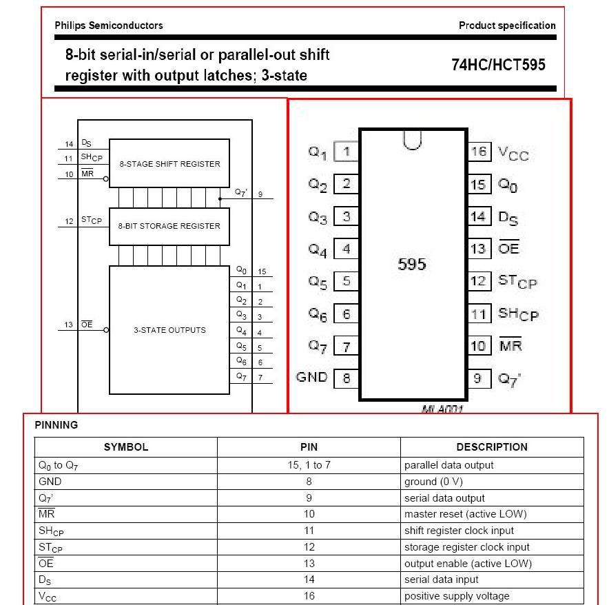
The datasheet for this thing is a bit ecclectic and near as I can figure I can hardwire OE(not) low and MR high to enable the thing....uh chip.
But...It seems I might need to actually play with MR instead?
Now for the meat....
Dishwasher has·7 main components
1--wash motor························· 2--Fill Valve (auto cutout float switch)
3--Drain motor/valve··················5--Soap dispenser solenoid
6--HI amp Heat Coil···················7--thermistor (pot readable)
7--120VAC from door·switch (door closed)
I add at minimum... button and piezo buzzer (3-15vdc).
I'm at 9 pins.· No good for bs1.· BUT loading the 8 bit unit gives me those 8·xtra outputs.·But it costs me·3 pins
P0--serial data out·· P1---Serial data clock·· P2---Storage Register clock
Note: I love the fact that this unit has a seperate set of registers for storage and shift.· Obviously, having various functions fire during data shift... (however briefly) could be problematic.
So the theory is simple.... set P0, pulse p1 & repeat 8 times.·then pulse p2 to "fire" the appropriate darlington pins.· this way I could change a LED (or flash it)·and not skip a beat in the operation of a motor.
Or not.· this is what brings me here.· While the darlington is firing the relays (12vdc) as it should.· The chip is a doorknob to all my attempts at communication.
my shift load routines (30% of the eprom...sigh)
the program·calls Dshift to load.· (Wlry & the rest are bits)
Sclock:
HIGH 1
PAUSE 100
LOW 1
PAUSE 100
RETURN
Dshift:
'load the shift registers
LOW 0
IF Wrly =0 THEN DS1
HIGH 0
ds1:
GOSUB Sclock
LOW 0
IF Frly = 0 THEN DS2
HIGH 0
DS2:
GOSUB Sclock
(Repeat thru 7 times (only caring about first 7 bits))
LOW 0
IF Rled =0 THEN DS7
HIGH 0
ds7:
GOSUB Sclock
'Now flip the storage bits
HIGH 2
PAUSE 50
LOW 2
RETURN
I added in the pauses to allow me to verify the data going out.·
i've tried setting all high and various high...and nothing out.....
Any ideas?·· Oh...instead of soldering the chip...I used a IC socket. for both ICs.
My dream was to use 3 pins on the bs2 and get at minimum 8 outs.· If later I wanted more...I could daisy chain in another shift register. (using the additional serial out provided)
Now since I'm driving relays and LEDs. I've linked the first 7·parallel outputs to a darlington.· The 8th·darlington I used for heater control and I sent a signal straight from the bs1 to trigger it.
Now the darlington ciruit works fine... but the shift register (hearafter refered to as·"chip")·remains dormant....
The datasheet for this thing is a bit ecclectic and near as I can figure I can hardwire OE(not) low and MR high to enable the thing....uh chip.
But...It seems I might need to actually play with MR instead?
Now for the meat....
Dishwasher has·7 main components
1--wash motor························· 2--Fill Valve (auto cutout float switch)
3--Drain motor/valve··················5--Soap dispenser solenoid
6--HI amp Heat Coil···················7--thermistor (pot readable)
7--120VAC from door·switch (door closed)
I add at minimum... button and piezo buzzer (3-15vdc).
I'm at 9 pins.· No good for bs1.· BUT loading the 8 bit unit gives me those 8·xtra outputs.·But it costs me·3 pins
P0--serial data out·· P1---Serial data clock·· P2---Storage Register clock
Note: I love the fact that this unit has a seperate set of registers for storage and shift.· Obviously, having various functions fire during data shift... (however briefly) could be problematic.
So the theory is simple.... set P0, pulse p1 & repeat 8 times.·then pulse p2 to "fire" the appropriate darlington pins.· this way I could change a LED (or flash it)·and not skip a beat in the operation of a motor.
Or not.· this is what brings me here.· While the darlington is firing the relays (12vdc) as it should.· The chip is a doorknob to all my attempts at communication.
my shift load routines (30% of the eprom...sigh)
the program·calls Dshift to load.· (Wlry & the rest are bits)
Sclock:
HIGH 1
PAUSE 100
LOW 1
PAUSE 100
RETURN
Dshift:
'load the shift registers
LOW 0
IF Wrly =0 THEN DS1
HIGH 0
ds1:
GOSUB Sclock
LOW 0
IF Frly = 0 THEN DS2
HIGH 0
DS2:
GOSUB Sclock
(Repeat thru 7 times (only caring about first 7 bits))
LOW 0
IF Rled =0 THEN DS7
HIGH 0
ds7:
GOSUB Sclock
'Now flip the storage bits
HIGH 2
PAUSE 50
LOW 2
RETURN
I added in the pauses to allow me to verify the data going out.·
i've tried setting all high and various high...and nothing out.....
Any ideas?·· Oh...instead of soldering the chip...I used a IC socket. for both ICs.
884 x 878 - 114K
Comments
I did have a wonder but the documentation didn't address it.. it says operation is 100 Mhz....wondering if the storage registers are dram based.... If so then I'd have to continuously strobe the data in..... But the loadout doesn't seem to say that...soo.....
These forums work best when you ask a relatively specific question and provide relatively concise background information for your question. Long rambling essays that end with "what do you think?" are a turn off for most readers unless the topic is a philosophical one.
www.parallax.com/StoreSearchResults/tabid/768/txtSearch/stampworks/List/0/SortField/4/ProductID/144/Default.aspx
www.parallax.com/tabid/272/Default.aspx
I didn't see any shorter way to ask this question.
I went back...(downloaded many of the associated PDFs)
Column #43, September 1998: Complimentary I/O
Addresses using a 8bit PAR to ser chip.· for robotics.
& uses a 8 bit ser to par for SERIAL I/O.
But that application isn't for long periods of data hold.
Wordy post aside..... my need for completion·is real.
I'm not asking for platitudes....I'm asking for advice.
Post Edited (sumdawgy) : 3/3/2010 6:10:22 PM GMT
I strongly suggest that you give up on the BS1 for this project and use a BS2 instead. The BS1 has very limited program storage and I don't think you're going to be able to fit what you need for your washing machine in the EEPROM. If you switch to a BS2, you'll also have enough I/O pins to control things directly.