

Prop Powered 8x8xRGB LED Matrix !
 Rayman
Posts: 16,457
Rayman
Posts: 16,457
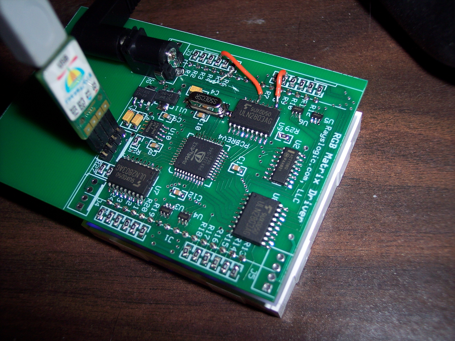
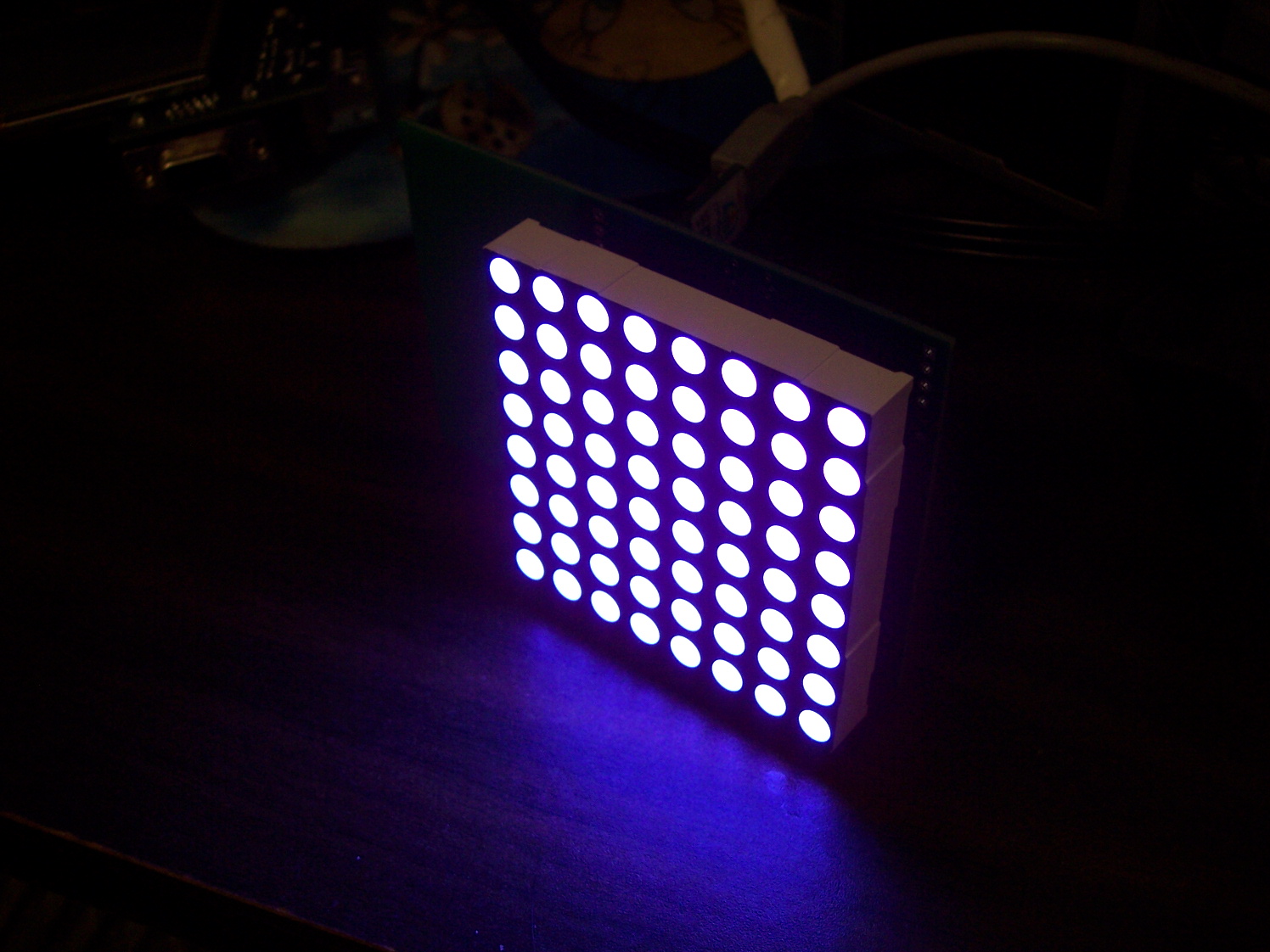
It works!!!· · I found a very nice PWM*8 driver in OBEX that is perfect for this...·
Thanks Phil Pilgrim !
I need to get resistors that better balance the colors though...· Right now, it's kinda purple with all on 100%
One dilemma is that if I put in resistors that maximize LED current, then it will be possible to damage the matrix
if the code isn't right...·
I think I'll start with resistors big enough to prevent damaging the display, even if bad code is used...
Also, this lets·one power the thing without a monster power supply...
▔▔▔▔▔▔▔▔▔▔▔▔▔▔▔▔▔▔▔▔▔▔▔▔
My Prop Info&Apps: ·http://www.rayslogic.com/propeller/propeller.htm
My Prop Products:· http://www.rayslogic.com/Propeller/Products/Products.htm
· I found a very nice PWM*8 driver in OBEX that is perfect for this...·Thanks Phil Pilgrim !
I need to get resistors that better balance the colors though...· Right now, it's kinda purple with all on 100%
One dilemma is that if I put in resistors that maximize LED current, then it will be possible to damage the matrix
if the code isn't right...·
I think I'll start with resistors big enough to prevent damaging the display, even if bad code is used...
Also, this lets·one power the thing without a monster power supply...
▔▔▔▔▔▔▔▔▔▔▔▔▔▔▔▔▔▔▔▔▔▔▔▔
My Prop Info&Apps: ·http://www.rayslogic.com/propeller/propeller.htm
My Prop Products:· http://www.rayslogic.com/Propeller/Products/Products.htm
1496 x 1122 - 886K
1496 x 1122 - 467K
Comments
Good work!
Jim
The PWM_8 ·has done me good also.
'Nice project (and very nicely done photos, BTW)! 'Glad the PWM driver found a home!
-Phil
But, since this thing doesn't need high frequencies (actually things got a little toasty when I upped the frequency), I made a custom driver that does all 24 columns in one cog.
One interesting note... I wasn't sure at first that 256 levels of linearly increasing duty cycle on an LED would give me the same levels that a VGA monitor would... But, I think I've convinced myself that this way is perfectly linear as opposed to monitors that need gamma corrections to be linear.
Still, I may have a look at adding more than 256 levels, just to account for device-device variations...
▔▔▔▔▔▔▔▔▔▔▔▔▔▔▔▔▔▔▔▔▔▔▔▔
My Prop Info&Apps: ·http://www.rayslogic.com/propeller/propeller.htm
My Prop Products:· http://www.rayslogic.com/Propeller/Products/Products.htm
I could dial the current down with the resistor choice, but then the max. blue wouldn't be as bright... I think the only way to solve this dilemma is to add more color levels...
▔▔▔▔▔▔▔▔▔▔▔▔▔▔▔▔▔▔▔▔▔▔▔▔
My Prop Info&Apps: ·http://www.rayslogic.com/propeller/propeller.htm
My Prop Products:· http://www.rayslogic.com/Propeller/Products/Products.htm
Which is your target with this ?, ·maybe some simple led driver will help you a lot with that issues.
▔▔▔▔▔▔▔▔▔▔▔▔▔▔▔▔▔▔▔▔▔▔▔▔
Regards.
Alberto.
But, I'm now thinking that I can make a very cost effective matrix driver by using the Propeller...
▔▔▔▔▔▔▔▔▔▔▔▔▔▔▔▔▔▔▔▔▔▔▔▔
My Prop Info&Apps: ·http://www.rayslogic.com/propeller/propeller.htm
My Prop Products:· http://www.rayslogic.com/Propeller/Products/Products.htm
Maybe using at least one of those, you could forget that issue, also get an 16x16pix matrix at a very low cost, where the propeller do almost the complete work.
I mean drivers like the MBI5024/25 or the TB62726, single led drivers without internal PWM.
I used them in a 256x8 matrix·in 24bit RGB color at 30fps of video succesufully, also I've enough memory and cogs to do a gamma control with them, and maybe 30bit color depth too.
▔▔▔▔▔▔▔▔▔▔▔▔▔▔▔▔▔▔▔▔▔▔▔▔
Regards.
Alberto.
So, in order to have 256 discrete levels for each of RGB and have RGB(255,255,255) be white, I'll either need to use different resistors to balance the colors. Or, I can improve the driver to be 10 bits per color.... I'll probably do the latter so as to allow maximum brighness in all colors even though red and blue need to be dialed down to make a nice white...
▔▔▔▔▔▔▔▔▔▔▔▔▔▔▔▔▔▔▔▔▔▔▔▔
My Prop Info&Apps: ·http://www.rayslogic.com/propeller/propeller.htm
My Prop Products:· http://www.rayslogic.com/Propeller/Products/Products.htm
And more, in my case I used only three variable resistors for all led drivers sharing their led current pins. I adjust the while balance easily turning the screwdriver in each variable resistor. The advantage of this, is that you have only one resistor for all leds of the same color, also the led drivers have an internal constant current circuit to achieve this.
I don't know, but if you want to use only a pchip, maybe you could imitate this, in each of your outputs, although I think that sounds not "cheap" and not practique.
Hum...I dont believe that.....the leds in your matrix display should have differents mc for each color to do that easy, I mean almost white color, when you drive the three leds, with almost the same current each.
·
▔▔▔▔▔▔▔▔▔▔▔▔▔▔▔▔▔▔▔▔▔▔▔▔
Regards.
Alberto.
Envio editado por (BTX) : 2/25/2010 11:08:13 PM GMT
if your PWM software is set up so it do Just Blue-LEDs at that cyckle.
adjust it so 0-256 is more like 0-240 etc
·
So, they would appear about white when driven with equal current.
But, these RGB matrices have nearly equal brightnesses for all the colors...
I'd guess that most people just want to scroll messages and don't care about color fidelity...
Tony:· The one big advantage my Prop driver board has is the abiltity to do a real 24-bit color per pixel with ultra-fast updates, so I'm going to push that as far as possible.
I want to make it expandable to show true-color photos...
But, just scrolling messages could be usefull too, so I think I'll need two type of drivers, one for max brightness in each color and one that gives white when given 255 for each color...
▔▔▔▔▔▔▔▔▔▔▔▔▔▔▔▔▔▔▔▔▔▔▔▔
My Prop Info&Apps: ·http://www.rayslogic.com/propeller/propeller.htm
My Prop Products:· http://www.rayslogic.com/Propeller/Products/Products.htm
Went to buy some more and everybody is totally sold out until May [noparse]:([/noparse]
They call the SMT package "SOL".· I think I know why now!
▔▔▔▔▔▔▔▔▔▔▔▔▔▔▔▔▔▔▔▔▔▔▔▔
My Prop Info&Apps: ·http://www.rayslogic.com/propeller/propeller.htm
My Prop Products:· http://www.rayslogic.com/Propeller/Products/Products.htm
▔▔▔▔▔▔▔▔▔▔▔▔▔▔▔▔▔▔▔▔▔▔▔▔
Regards.
Alberto.
I can't find any pricing on your example...
You would need at least two of them to drive the matrix.
The Prop and three ULN2803s can do the job·and much more for about the same price...
PS:· I·just found·some Chinese ULN2803 on Ebay (not sure how legit they are...)
▔▔▔▔▔▔▔▔▔▔▔▔▔▔▔▔▔▔▔▔▔▔▔▔
My Prop Info&Apps: ·http://www.rayslogic.com/propeller/propeller.htm
My Prop Products:· http://www.rayslogic.com/Propeller/Products/Products.htm
It only uses up 2 cogs to run the display driver and a third spin cog to generate the pattern. The driver can be slimmed down to 1 cog, but this lowers the refresh rate below 1000 with the prop running at 80 MHz.
For larger displays driver chips are totally worth it. The TLC5940 can go up to 12 bit color depth per channel (36 per full color pixel), has built in color correction and an eeprom to store the values, can be daisy chained, built in current control, and they are dirt easy to use. I did discover that each color channel does need some form from isolation from the other to keep colors accurate. Whenever the red color channel is using a lot of current on the display, the blue and green colors get dimmer due to the low vf of the red LEDs clamping the voltage. This could be solved by a bunch of resistors or separate voltages to each color, but that's a problem when the supply voltage for each pixel (aka RGB LED) is tied together to form common anode. I'm betting the LED unit you got was from sparkfun, which should be common cathode (not to trash sparkfun, but they are overpriced too). I have no idea why they sell those, most display drivers require common anode LEDs. Anyway, if you did get common anode units and you wish to make a larger display, driver ICs would be the way to go.
Video of teh display: www.youtube.com/watch?v=nYMMWTVTndk
I attached the code for my display, both programs generate the arrow effect in the video. The driver in the first one runs in 1 cog, the second one runs in two, but a lot faster. It's kinda hard to read; I'll comment it if anybody asks.
·
1: The prop is way to powerful just to drive one, so driving 2 (or 4) Matrix should be evaluated.
·
2: 1 cog·and 2 pins for·communication with master display mcu.
·
·
3: 6 cogs in a 2x matrix,·where·each cog is responsible to drive each R,G,B cathode.
··· allows fine tuning·(gamma correction)·in software for each color component.
·
·
4: 28 pins for multiplexing, the type where each RGB component can be duty-cycled individually is important.
···
····a: Charliepleing with npn transistors, 9 pins for regular 1 color LED. 12% duty cycle.
······· how to deal with that its 3 cathode for each pixel (x2 for a dual matrix) without running out of pins?
·
·
···· b: Gridplexing, there are 8·colums for common anode, so 3 pins for·a 3-to-8 decoder (74HC238)
·········best way to deal with the 48 cathode's (dual matrix) using remaining 25pins?
········ Individually fine tuned lenght·duty-cycle·for each RGB component is important.
·
Post Edited (tonyp12) : 2/28/2010 6:59:11 PM GMT
I've done a lot of experimenting with different current limiting resistor values and think I've finally decided on some that are the best comprimise between power requirements and white balance. The total current draw with all LEDs on max is now 430 mA. In "white balance mode" the total current with all LEDs on max is 330 mA. So, a 6V, 500mA power supply works well. (It can also be powered directly from a USB 5V source, but the output of the LDO regulator drops to 4V. So, this is probably not an ideal way to go). My 9V supply works for a while with all LEDs on full, but the 5V LDO regulator goes into thermal shutdown after a couple minutes.
Made some progress with the driver too. Settled on 256 levels per color, or 24-bit per pixel color. But, red and blue are dialed down to a max of about 100 in "white balance mode". The driver is now double-buffered and can scroll easily.
I've found a way and room to add 8 resistors to set a unit ID for making a larger display. So, this will allow for up to 256 units to be combined using the same Prop code in EEPROM. In this way, a 128x128 pixel display can be controlled by a single Prop Plug. Or, any of the units could be defined as master to allow internal control. There are headers to daisy chain RX, TX, and power.
I was able to almost get a decent video here by sorta tricking the camera, looking away from the matrix...
Very nice! I have the same small matrix but everything that has been said in this thread is over my head.
The only thing I understand is 256 levels = 24bit per color because 8 x 3 = 24.
Is there anyway you could explain how this all works a little simpler? do you go through all the LED's quickly updating them? Or row by row? or?....I just need help understanding how your getting it to work.
If you were to stop time how may LED's would be lit at a given time if in real time the display was showing white? 1led or a row or column?
any materials I should read?
There are essentially 24 columns (8 each of R,G&B). Each column is connected to a Prop Pin (via a darlington to increase current carrying ability).
There are 8 rows, but only one is selected at a time.
So, the code cycles through the rows, one at a time, and the Prop uses 24 pins to decide which leds in that row are turned on.
Make sense?
YUP!
So the brightness levels of each R,G, & B are set how? Do you sit on a row PWMing the colors for a bit before moving on to the next row or does it just pulse each color once for a certain time period before moving to the next row?
does that make sense?
Ok so for example if you sit on a row for 255nS then the level is just how many nS it is on? then on to the next row?
gotcha...
So you are also using all 32 pins? Or are you using some type of decade counter to select the rows?
Thanks!
I'm using 24 pins for colums, and 4 pins with a 3:8 demux, so that's 28 out of 32 pins.