

BS1USB serial control over its USB with terminal
 spamer
Posts: 2
spamer
Posts: 2
Hello,
I like to control BS1USB using USB serial port. I found, that there is no connection from USB serial to software using SERIN.
So I connected the USB serial output to P3 with 10K resistor. See attachement. Warning - changing the board voids warranty.
It receives the data, but after about 1 second of data been received the CPU restarts itself.
Is there some solution how to control software with USB serial terminal?
Juraj
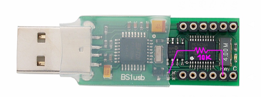
858 x 319 - 67K
Comments
Simple program:
Main:
LOW 4 ' connected led between VDD and P4 light on
GOTO Main
When send e.g. "00" to terminal on 1200, then led gets dark for about 1 second and then get light back. BS1USB is probably restarted.
Terminal reads every char sent - received data "5B 5B 5B 5B 5B 5B 5B 5B 5B 5B 5B 5B 5B 5B 5B 5B F9". Probably some debug mode is activated.
I think, that CPU is still is debug mode, that expects only new firmware on the serial line. When incorrect char comes ("0"), then it is automatically reset, what is not really expected. There should be added some magic sequence to activate CPU reset, not just single char "0".
I used the same transformation of spamer aading the resitor 10K , serin works fine but serout send full of control caracters to the computer !
do you have idea what's wrong?
You're probably forcing the Stamp to reset by short-circuiting the power supply. If you connect an ordinary LED between an I/O pin and, say, Vdd, the LED will short circuit between the I/O pin and Vdd. The Stamp's I/O pin (if it doesn't burn out) will supply at most 20-30mA to the LED. That still may be enough to cause a drop in Vdd to below the point where the Stamp will automatically reset (about 4.2V). Solution: Use a 470 to 1K resistor in series with the LED to limit the current to something reasonable.
avicenne,
You really have to supply a copy of your program and a diagram (schematic) of your circuit. Otherwise, we're really just guessing what's wrong. See below:
Thanks for your quick reply
the program i use for test is just the template on parallax CD
' SEROUT.BS1
' This program transmits the string "ABCD" followed by a number and a
' carriage-return at 2400 baud, inverted, N81 format.

' {$STAMP BS1}
' {$PBASIC 1.0}

SYMBOL  SOut            = 1
SYMBOL  Baud            = N2400

SYMBOL  value           = W1


Setup:
  value = 1

Main:
  SEROUT SOut, Baud, ("ABCD", #value)
  value = value + 1
  PAUSE 250
  GOTO Main
  END
When i connect the BS1 thrue PIN1 to serial cable and then to the computer evrything works fineComputer receive the data correctlly
But when i do the transformation of spamer With the resistance 10K the data pass by FTDI chip on USBBS1 , then by a USB cable is connected to the computer.In this case the data received by the computer is wrong full of 8c and 9c are received by the computer.
In my opinion the solution is on the FTDI chip . am i wrong?
the other solution is DEBUG Viewer but it replace serout not serin.
I am going to try to find a solution for this communication .
Otherwise i think We must completly migrate to the BS2.
If you have idea about this communication it will be appreciate
With my thanks from France
You can use the DEBUG statement to send data via the programming connection to the PC. The Nuts and Volts Column #20 describes the format of the data packet that is sent to the PC.