

MAX4410 Troubleshooting
 Lord Steve
Posts: 206
Lord Steve
Posts: 206
The MAX4410 is the audio amp used on the Propeller Demo Board.· I have one in a project but when the (32-ohm) headphones are plugged in, the·power supply rail (from a Texas Instruments TPS61070) does not come up to 3.3V.· When the headphones are not plugged in, the power supply rail reaches 3.3V and the project turns on.· Then when I plug the headphones in, the project shuts off.· (The rail goes down to like 1.5-2V again).· Interestingly, when I use a wall wart power supply for the 3.3V rail, the project powers up with the headphones plugged in.· So, I'm thinking maybe it's something like in-rush current at startup.· Another thing I noticed is that at power up, there is current going to the speakers of the headphones.· (I can see the speakers move for sure.)· I don't think that's right because there is not supposed to be any DC bias from the MAX4410.· There is a filter in front of each input to the MAX4410, and the capacitor from those filters should block any DC input to the MAX4410.· (So, it doesnt matter what the state of the Propeller output pins to the audio circuit is.)· Right?
According to the MAX4410 datasheet, the output power to a 32-ohm Load is 65mW.· 65mW divided by 3.3V = ~20mA.· For two channels, Left and Right, that's about 40mA output current.· (Right?)
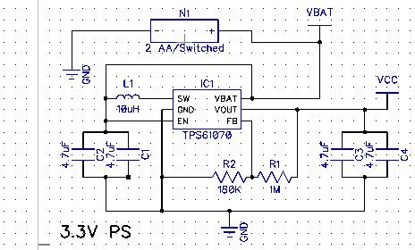
According to the TPS61070 datasheet, the (maximum) output current at 3.3V output for 2.9V (let's say the 2 AA batteries are a little drained) is close to 400mA.· I'm pretty sure that the rest of the project is not taking 360mA from the 3.3V supply.
I copied the schematic for the MAX4410 circuit from the Propeller Demo Board.
Any ideas?· I'll try just one speaker and see if that works, but I wanted to get this in the pipe.
Thanks.
Datasheets below.
Edit:· Added a picture of the 3.3V power supply circuit from the project.
Post Edited (Lord Steve) : 2/18/2010 2:59:25 AM GMT
According to the MAX4410 datasheet, the output power to a 32-ohm Load is 65mW.· 65mW divided by 3.3V = ~20mA.· For two channels, Left and Right, that's about 40mA output current.· (Right?)
According to the TPS61070 datasheet, the (maximum) output current at 3.3V output for 2.9V (let's say the 2 AA batteries are a little drained) is close to 400mA.· I'm pretty sure that the rest of the project is not taking 360mA from the 3.3V supply.
I copied the schematic for the MAX4410 circuit from the Propeller Demo Board.
Any ideas?· I'll try just one speaker and see if that works, but I wanted to get this in the pipe.
Thanks.
Datasheets below.
Edit:· Added a picture of the 3.3V power supply circuit from the project.
Post Edited (Lord Steve) : 2/18/2010 2:59:25 AM GMT

Comments
Any thoughts?·
I'm also looking at using the MAX4410 in a design - how did it work out for you in the end? The alternatives either don't reference to ground, or are more difficult to solder.
As to why the demo board doesn't have feedback resistors - It uses the MAX4411, which is very similar to the MAX4410 but brings those feedback resistors inside the chip for fixed gain
thanks
tubular
For instance I wasn't able to find a solution at mouser or RS- components..
Massimo
http://uk.farnell.com/roth-elektronik/re933-02/adaptor-smd-tssop-14-0-65mm/dp/1426181
It's very expensive, though. I'd just make my own.
The most friendly one I found was in an SOIC 8 package, the LM4910. Rochester electronics has some in stock.
http://www.national.com/mpf/LM/LM4910.html#Overview
I have problems finding hand solderable chips available in single quantities.
While soic, msop and so on are OK, a package like the LLP is out of my reach, and the seller I usually buy from are not stocking this family of chip in a soic style package.
Massimo