

IR-augmented Echo-location with the Ping)))
 Phil Pilgrim (PhiPi)
Posts: 23,514
Phil Pilgrim (PhiPi)
Posts: 23,514
One method that's often used for locating a robot in a confined indoor space involves ultrasonic transponders at known locations that can be polled individually by the robot. By measuring the ultrasonic pulse's time-of-flight from each transponder, its distance can be ascertained. A triangualtion computation can then be performed to get the bot's location.
As it turns out, the Parallax Ping))) can be used in both the transponder units and the robot's time-of-flight sensor, without any electrical modification. For a long time, I hadn't thought the latter (passive sensor) was possible, since the Ping))) has to send an ultrasonic pulse to activate its receiver. But that requirement is easily mooted by covering the transmit transducer so no sound can escape. Then, when the Ping's input pin is pulsed, it will simply wait for an echo that can never return (since no pulse was emitted), or for a pulse from another Ping.
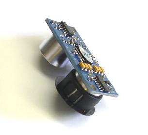
With this in mind, I made a trip to the local hardware store to look for something to block the transmit transducer. What I found was a plastic hole plug (for 3/4" holes) that could be mis-applied as a cap to fit the transducer very snugly. A test with the cap in place confirmed that no pulse could escape; hence no echo would be received. Here's a photo of the Ping with its cap:

The overall idea is this:
Scanner: The "scanning" unit sends a coded IR signal to transponder "A".
····Transponder: The transponder waits for its particular signal to be received via IR.
Scanner: As soon the scanner has sent the coded signal, it pulses its Ping I/O pin to activate the "echo" detection.
····Transponder: When the transponder receives its coded signal, it triggers its Ping, which sends an ultrasonic pulse.
Scanner: The Ping waits for an "echo", in this case a pulse from the transponder. The amount of time it waits is proportional to the transponder's distance.
Scanner: The same procedure is repeated for transponder "B".
Once the times from both transponders are known, their distances can be computed. Assuming you know the distance between the two transponders, you can compute the scanner's location in Cartesian coordinates by triangulation. Here's an illustration:

The relevant formulae are:
····x2 + y2 = a2
····(d - x)2 + y2 = b2
These two equations can be solved for the two unkowns, x and y, using the known values for a, b, and d. (This is left as an exercise for the reader, but it's not that hard. The difficult part will be converting the resulting expressions into PBASIC code.)
To get any distance from an IRED, it's necessary to trigger it with more current than a BASIC Stamp pin can provide. Here's a circuit I used to boost the current:

Although the IR receivers are fairly isotropic (direction-insensitive), the IREDs themselves are highly directional. The ultrasonic transducers are also direction-sensitive, but it's not so bad when they have a transponder blasting at them, rather than a much more feeble echo. For these reasons, I decided to mount the scanning Ping and IRED on a rotating turret on my BOE-Bot, so that the tranponders could be scanned for in a 180-degree sweep. (I fabricated a custom turret from acrylic, but I'm quite sure that Parallax's Ping scanner could be pressed into service to hold the IRED, with only minor mods or additions.)
The two transponders were built up from BOEs, Pings, and IR receivers, and their circuitry does not vary from that presented in Parallax's documentation. The BOEs are gross overkill for this, but they're what I had, and they're conveniently powered from 9V batteries, thus easy to place in the "arena".
Here's a composite photo of my scanner and one transponder:

The PBASIC code for this project is attached as a zip, below. As it stands, the project is incomplete, since nothing has been done to incorporate the distance info into a real navigation program. My objective was mainly as a feasibility study, to see if echolocation could be performed with standard Parallax parts and minimal alteration. To this limited extent, I feel that the experiment was a success.
Thanks,
-Phil
Update (2010.02.16): Corrected a typo in one of the BS2 files.
_
Post Edited (Phil Pilgrim (PhiPi)) : 2/16/2010 8:16:02 PM GMT
As it turns out, the Parallax Ping))) can be used in both the transponder units and the robot's time-of-flight sensor, without any electrical modification. For a long time, I hadn't thought the latter (passive sensor) was possible, since the Ping))) has to send an ultrasonic pulse to activate its receiver. But that requirement is easily mooted by covering the transmit transducer so no sound can escape. Then, when the Ping's input pin is pulsed, it will simply wait for an echo that can never return (since no pulse was emitted), or for a pulse from another Ping.
With this in mind, I made a trip to the local hardware store to look for something to block the transmit transducer. What I found was a plastic hole plug (for 3/4" holes) that could be mis-applied as a cap to fit the transducer very snugly. A test with the cap in place confirmed that no pulse could escape; hence no echo would be received. Here's a photo of the Ping with its cap:
The overall idea is this:
Scanner: The "scanning" unit sends a coded IR signal to transponder "A".
····Transponder: The transponder waits for its particular signal to be received via IR.
Scanner: As soon the scanner has sent the coded signal, it pulses its Ping I/O pin to activate the "echo" detection.
····Transponder: When the transponder receives its coded signal, it triggers its Ping, which sends an ultrasonic pulse.
Scanner: The Ping waits for an "echo", in this case a pulse from the transponder. The amount of time it waits is proportional to the transponder's distance.
Scanner: The same procedure is repeated for transponder "B".
Once the times from both transponders are known, their distances can be computed. Assuming you know the distance between the two transponders, you can compute the scanner's location in Cartesian coordinates by triangulation. Here's an illustration:
The relevant formulae are:
····x2 + y2 = a2
····(d - x)2 + y2 = b2
These two equations can be solved for the two unkowns, x and y, using the known values for a, b, and d. (This is left as an exercise for the reader, but it's not that hard.
The difficult part will be converting the resulting expressions into PBASIC code.)To get any distance from an IRED, it's necessary to trigger it with more current than a BASIC Stamp pin can provide. Here's a circuit I used to boost the current:
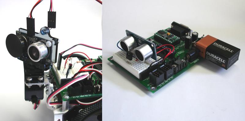
Although the IR receivers are fairly isotropic (direction-insensitive), the IREDs themselves are highly directional. The ultrasonic transducers are also direction-sensitive, but it's not so bad when they have a transponder blasting at them, rather than a much more feeble echo. For these reasons, I decided to mount the scanning Ping and IRED on a rotating turret on my BOE-Bot, so that the tranponders could be scanned for in a 180-degree sweep. (I fabricated a custom turret from acrylic, but I'm quite sure that Parallax's Ping scanner could be pressed into service to hold the IRED, with only minor mods or additions.)
The two transponders were built up from BOEs, Pings, and IR receivers, and their circuitry does not vary from that presented in Parallax's documentation. The BOEs are gross overkill for this, but they're what I had, and they're conveniently powered from 9V batteries, thus easy to place in the "arena".
Here's a composite photo of my scanner and one transponder:
The PBASIC code for this project is attached as a zip, below. As it stands, the project is incomplete, since nothing has been done to incorporate the distance info into a real navigation program. My objective was mainly as a feasibility study, to see if echolocation could be performed with standard Parallax parts and minimal alteration. To this limited extent, I feel that the experiment was a success.
Thanks,
-Phil
Update (2010.02.16): Corrected a typo in one of the BS2 files.
_
Post Edited (Phil Pilgrim (PhiPi)) : 2/16/2010 8:16:02 PM GMT

Comments
Between this, the Stingray and Ken's plywood platform, I predict a brisk uptick in PING sales. Buy P'lax stock NOW.
Didn't the wood platform Ken sent you have 8 or 10 PINGs on it? My Poor Cousin robot can't afford all those fancy ultrasonics for range detection. We're looking at sensors made from tin-foil pie pans, a spoon, and an old AM radio. [noparse]:)[/noparse]
▔▔▔▔▔▔▔▔▔▔▔▔▔▔▔▔▔▔▔▔▔▔▔▔
·"If you build it, they will come."
Clever idea!
Do you or anyone else know of ultrasonic emitters that might be considered as point sources rather then having than having directionality?
Graham
Yes, Ken's platform has 10 Pings. (I had to borrow one of them for this experiment.)
Graham,
You've anticipated my next experiment! I believe that the Ping transducers can be made much less directional by affixing apertures (vertical slots, in this case) in front of the them, causing dispersion. What I'm not sure of, though, is how that will affect their range.
In the reverse sense, I had also hoped to be able to narrow their cone of acceptance by using a Fresnel zone plate aperture (acoustic lens). But, so far, the required working distance has been a problem, since the the Ping picks up an echo from the lens itself and stops listening. The same thing happened when I fabricated a parabolic reflector for the Ping: 'couldn't get it close enough to be in the Ping's "deaf zone". And putting a barrier between the transmit and receive transducers has proven ineffective in preventing self-reflections, for some reason.
I've been looking for transducers with wide beam patterns, but with little success. I was hoping to use them to design a Prop-driven phased array which could be steered electronically, rather than having to rotate one mechanically. But it's pointless to attempt that with directional transducers.
-Phil
They talked about sound being a bit like light and the fact he was seeing with sound but really it would not be possible for him to image anything as such, the ears only giving a little directionality. However in our world of straight vertical surfaces (walls, doors, etc) I got the impression that perhaps a lot of the sounds you get back are fairly stereotyped, even I could tell my bathroom door was open when I spent some time in a blindfold around the house. So I wanted a clicker to play with, I'm interested in simplified navigation around buildings.
I have toyed with taking a transducer apart to see what can be done with it.
Graham
Thanks so much for posting this! I feel a trip to the hardware store coming on.
Can't wait to see your Ping))) with a set of Kanye Sunglasses!
▔▔▔▔▔▔▔▔▔▔▔▔▔▔▔▔▔▔▔▔▔▔▔▔
Whit+
"We keep moving forward, opening new doors, and doing new things, because we're curious and curiosity keeps leading us down new paths." - Walt Disney
Duffer
▔▔▔▔▔▔▔▔▔▔▔▔▔▔▔▔▔▔▔▔▔▔▔▔
Any technology, sufficiently developed, is indistinguishable from magic.· A.C. Clark(RIP)
-Phil
_
Post Edited (Phil Pilgrim (PhiPi)) : 2/19/2010 5:41:49 AM GMT
As always, very impressive.· I have read·several examples of various·triangulation methods, but this is the first example I've seen of a working model.· I'm curious about the range and accuracy of your tests.· I'm also curious about the source of the gear set you used.
Thanks for sharing.
agfa
I haven't done any tests on accuracy yet. At this point, it's mostly just a proof of principal for the hardware. I made the mount (from acrylic) and gearset (from Delrin) using a laser cutter. The gear involutes were created in Rhino using a macro, then exported to CorelDraw. The design was finished in, and output to the laser cutter from, Corel.
-Phil
I believe the ping has a narow beam angle possibly 10 degrees, and an accurate range to about 3 meters.·· For the robot to perform tri-angulation, it would have to be in the area where the two beams cross, which would only be a small area anyway.
I'm sure there are some very clever people out there who could work around this problem.
I think the same theory could apply using IR leds and sensors, since you can use multiple IR leds on ech transmitter to give· a wide coverage angle. Then using the angle of detection from the reciever (using a servo) to·do the triangulation without any distance measurements.
Seeing new ideas always gets me thinking !!!·
I would bet that the apparent range is at least doubled since the ultrasonic signal is going from Ping1 to Ping2 instead of Ping1>>reflection>>Ping1. The beam width may also enjoy an effective increase since there is no reflection absorbtion.