

Input needed on circuit design
 bambino
Posts: 789
bambino
Posts: 789
The project I'm working on is finished, but has failed to meet requirments. So Maybe someone here can help.
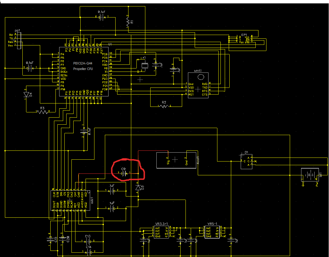
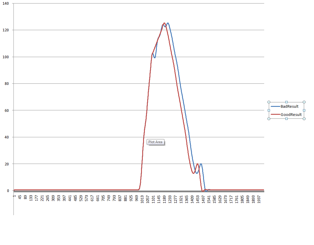
The device below is a wireless upgrade to an existing wired device that measures impact via an accelorometer, and transmits the results back to a PDA. The problem, as I see it, is in the capacitor that filters the signal back to the AD converter. But that is why I'm asking here. I've tried some other capacitor values with no success. The circuit itself is approved by the makers of the accelorometer but as seen in the results picture I'm not getting the same results that the predecessor is giving.
The accelorometer was made to be imbedded in the tips of drill bits for oil rigs and maybe 30 g errors are acceptable for them. In my application, 3 to 4 gs is about as far as it can tolerate.
I have since added temperature compenstion to the circuit and that removed some error, but maybe you see something else!
I'm sure I'll leave something out that you need to know in order to evaluate the board, so please just ask.
The diode feeding the sensor is a constant current diode the takes 5 volts, and at 1 G, outputs 2.5 volts. Itmeasures + or - 500G's at 2mVper G.
Thanks for any and all input
The PDF for the converter doesn't want to open for me so here is a link to the site.
http://www.maxim-ic.com/quick_view2.cfm/qv_pk/4943
Post Edited (bambino) : 2/14/2010 10:43:15 PM GMT

Comments
What's happening in the real world at the "shoulder" and at the peak? Is the shoulder an impact?
Just on the surface of it, I don't think the capacitor value could smooth things sufficiently to make those two waveforms match, particularly at the shoulder. It looks more like some kind of physical dynamic effect. How is the sensor mounted in the bit, is there some kind of damping material?
cheers
tubular
The predesessor actually presents a smooth bell curve during a drop.
Real World: The whole bell curve represents the impact of my device on the ground from a two foot drop"roughly"
How mounted in the bit: My device isn't mounted in a bit, that is just what the accelerometer was orignally designed for!
The accelorometer, along with the circuit, are mounted inside a cylindrical metal mass of 20 lbs and dropped on the surface to be measured for impact resistance.
I think you're going to need a drop rig to test it with that method. If the head of the 3205B is exposed, you could invert it, and use a "calibrated" mass dropped down a tube on to the head.
Edit: I can't find the datasheet for this Dytran 3205B. Do you have a link to it?
Post Edited (jcwren) : 2/14/2010 11:54:50 PM GMT
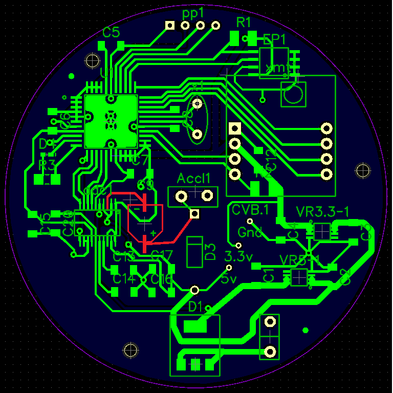
Below is pictures of the finished device!
How many runs have you made, and are the results always consistent? The first dip in the blue line could possible be binding in the drop rig. The pictures show the rig sitting on What looks like a tile or linoleum floor, neither which are ideal surfaces. You really need something that's a couple feet of solid concrete, like a loading dock bay.
Although with only the sample shown, it would be hard to make this call, but at 16-bit sampling with a 4.096 volt Vref, you're looking at 62.5 uv (microvolts!) per bit. ANY noise in the ground plane will mess with your conversion accuracy. Luckily, you're using a battery which is more idea than a switching supply, but any variance in current draw could be coupling noise into your system. Are you doing any smoothing, or taking only the top 12 or 14 bits of the A/D for your values? 30g represents 60mv of noise, which is not really all that much as power supply noise goes. Have you put a 'scope on the power and ground planes?
I think a bit more detail overall is going to be needed.
We don't drop on concrete, on purpose anyway! the result of 20lbs steel on solid conrete is over 500G and will void our product. The typical range for drops on play surfaces is from 80 to 200 G's.
The signal is using the full 16 bits at around 56K samples per second. There is an iir filter in my code simulating a 4 pole low pass butterworth filter.
The Regulators are rock solid, and feed by circuit protection diodes. I have scoped them out on the bench, but there is no way of scopeing them out during a drop.
I have high hopes for the next prototype, but not until I can get this failure figured out!
Consistant? Yes, Since I put temperature compenstion in the results have been consistant.
It shows the results of approx 20 drops onto a sample mat at various temperatures.
This piticular test was to see if my temperature compensation was on the mark.
It's still a little off but the error in G's is still an issue.
Although the error in this set would probably pass, it is the best results I've seen, the error is not porportional to temperature.
No, the accelorometer is molded inside the steel with heat cured epoxy and the circuit is encased in PVC that is bolted to the inside well of the steel!
Nothing to slosh around and cause dynamic readings.
Its hard to tell from the timing but is there a chance there is a shockwave bouncing through the steel, and this new accelerometer is more susceptible to the shock wave than the previous model?
Do you have the option of running a test with a cushionable material (eg rubber or silicone) instead of epoxy? It may reduce the peak G's but make things more consistent?
Because the drop is taking place inside a cylinder, I would question the role that airflow might play during a drop. See my attached sketch. In Case 1 the cylinder has air flowing around it very differently than in Case 2. If the clearance between the seals is tight, then you might have to worry about the seals creating momentary friction. But if the drop cylinder can rattle around a little as it makes its descent, then not only will you have momentary frictional effects from the seals but you also might experience erratic airflows that could affect your results. How the air moves out of the clear cylinder and/or around the descending cylinder might make a difference in the speed of its descent.
just my 0.0002 cent worth
The circuit at the top of the thread is the one that is inside the head now without the addition of a temp sensor added to one of the prop's pins. There is no schematic for that as I added it to the current board as an after thought. The circuit works, just not as accurately as I would like.
The finished head, electronics and all is exactly 20lbs. not 19.8.
Tubular, The things we drop on vary from rubber to polyeurathene during testing because the constant dropping doesn't effect there shock absorbance over time. That allows me to expect a certain reading while I'm testing. The end product for testing is playing fields!
The Bottom of the head is flat.
Electricaye, There is a float level embedded in the tube around the top collar to center the head prior to dropping.
Post Edited (bambino) : 2/15/2010 5:34:36 AM GMT
1) The input impedance of the ADC is 17K...the RC time constant for this coupled with the 10uf capacitor is 0.17 seconds...you will get some error (G underestimate) due to this. The good news is that this can be easily compensated for in your calculations. If you use the Taylor expansion approximation for e^-x for small x then for the RC value of 0.17 you will get about 3 Gs per ms error caused by capacitor charging effects...that is if the impulse duration from start to peak is 5 ms then you can expect ~15Gs of underestimation. How long is the impact duration from start to peak?
Edit: Seems I was overzealous in the above calculations and made a pretty large error...the underestimation error would be more on the order of 2 or 3Gs for the 5 ms example NOT 15Gs. I am guessing that for the set-up (drop height/results) the time is on the order of 2 ms, so the underestimation error due to the ADC-capacitor pair is likely to be negligible.
2) What of the calibration for the accelerometer? The sensitivity specification states +/- 10%; I am guessing the sensor came with a calibration sheet.
3) Are you supplying very nearly 4 mA to the accelerometer (have you measured this directly with a DMM)?
Post Edited (Miner_with_a_PIC) : 2/15/2010 5:56:02 PM GMT
I am at work now. But Promise to answer soon
Thanks again
The drop takes roughly 50% of that and half that is 5.5ms for start to peak, Soft G mats will be longer (8 ms) and hard surfaces shorter, say 3 ms.
Yes there is a calibration sheet I, though I don't have it in front of me. The posted datasheet above has the specs. page2
The constant current diode is regulating the current. I am not sure what it is supplying.
The error coupled with the noise jcwren spoke of could account. for the error
Can you think of a capacitor that would give less error?
Graham
No , not recently. Naturally I did before I wrote and tested the filtering code and I think once after that during a rewrite!
I did once test the output without the capacitor. All I get is a spike, which would be allright with me, but the owner of the patent wants the graph to look the same as the old device so as not to confuse customers.
It would be good for me to ouput the raw data along with the filtered for awhile just to rule that out though.
Thanks
www.dytran.com/img/tech/a6.pdf
The cap is a high pass filter (combined with input impedance) so it is unlikely to remove the oscillations but by lowering the cut off you may recover some lost signal from the lower frequency end. If your readings are lower than expected this might help.
Graham
My readings are actually high in the target area, and get closer to dead on at the max(500).
The posted readings where calibrated at 45% of the raw data, and they are·about 5 % higher than the predessor. Close enough for testing the temp sensor though. The calibrated G's for that drop is 118. I'm refering to the chart about halfway down the 1st page.
In the next prototype, I am going to make use of the differential channels and feed the negative input with the output from a second constant current diode. This should cancel any power supply noise and zero my readings without haveing to adjust in code.
Thanks for the link though I'll give that a read for sure. Even though my readings are high I still feel my capacitor is too big.