

Mouse Sensor Module in Development -- Draft documentation posted (8 Mar 2010)
 Phil Pilgrim (PhiPi)
Posts: 23,514
Phil Pilgrim (PhiPi)
Posts: 23,514
Ken Gracey obtained some sample mouse sensor chips and their associated lenses/lightguides on a recent trip to China. He approached me with a request to help him develop an optical mouse sensor module. The idea was to have something that would interface to BASIC Stamps and Propellers and that would detect X and Y motion from a contact or near-contact surface. The chips and optics are mass produced for computer mice, but they're not terribly user-friendly for experimenters. Although the chip comes in a DIP, it's bottom-looking, requiring a board cutout, and has staggered 2mm-spaced pins. The optics consist of a single, clear injection-molded piece of plastic with no mounting holes. The chip docs show how all the pieces are supposed to fit together using a custom injection-molded base. But this isn't much help for the do-it-yourselfer.
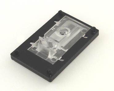
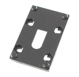
I knew the mechanical part would pose the biggest challenge, and I wan't about to design any injection-molded parts. I was counting on a recently-acquired laser cutter to design an easily-fabricated base assembly when I agreed to work with Ken on his project. It actually turned out to be fun, as most such challenges do. The optics have a very short focal length and about a 0.2mm depth of field. This means that the lens assembly has to be rather precisely positioned over the surface it's looking at to obtain a focused image. But good fortune smiled on me for once. By stacking a couple laser-cut pieces of Plexi (or Delrin) and fastening them together with plastic push-pull snap rivets, I could not only get the right height, but create a base with a pocket for the lens, smooth, slick feet for gliding on the surface, alignment pins for the PCB, and hex-shaped pockets to capture the nuts required to hold the PCB in place. Here are a couple photos of the base:


The PCB is attached to the base with #2 screws and nylon spacers. Bivar sells spacers in length increments of 0.005", so it wasn't difficult getting some that set the PCB at just the right height for the chip to be in contact with the lens. The nut pockets in the base not only keep the nuts from protruding, but they also eliminate any need for a wrench during assembly.
So the mechanical part, after much trial and error, came together with more than a little luck and serendipity. The electrical interface proved to be just as "interesting", however. The sensor chip requires +5V, Gnd, and two signal lines: clock and bidirectional data. That's four pins. The easiest-to-interface cables that Parallax offers are are their three-conductor "servo" extension cables. Now, I could have just slapped an AVR on the board to drive the sensor chip and provide a one-pin bidirectional serial interface; but Ken and I both agreed that that would not only add too much to the cost and size of the module but that it would insulate the user too much from the sensor's native interface. I still wanted to use the servo cable, though, so we decided to include a 2x3 header on the board with a configurable pinout and one very interesting option.
It turns out that the sensor chip wants to have a clock that's mostly high but pulses low. This provides an opportunity to supply power to the module on the clock line, reducing the conductor count to three, as shown in the following partial schematic:

I've tested this method, and it works fine. As a bonus, since the input clock is inverted, and since the SHIFTIN/OUT instructions in PBASIC support only positive-going clocking, it allows these instructions to be used with the mouse module, instead of having to bit-bang it. This won't be the only connection option, but it's the one that uses the least amount of cabling.
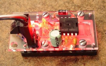
In order to test everything together before committing to a PCB, I laser-cut a mockup from acrylic, to which I hot-melt-glued the components and underneath which I wired the circuit. Acrylic doesn't make a very nice circuit board, BTW. Its low melting point means you really have to work fast with the soldering iron; and heaven help you if you need to use solder wick! But, despite numerous melt "adventures", I got it to work. Here's what the whole initial proto module looks like:


The overall X/Y dimensions are 1.8" x 1.0". The PCB overhangs the base by 1/4" to allow access to the PCB's two mounting holes in the end. You'll notice that the board uses all through-hole components. This is because it will be offered in kit form. Ken and I both agreed that this is the best way to keep costs down and provide the maximum value to the end-user.
Now that I see how everything fits together, I can lay out the PCB and get some protos made. More later!
-Phil
_
Post Edited (Phil Pilgrim (PhiPi)) : 3/9/2010 3:16:26 AM GMT
I knew the mechanical part would pose the biggest challenge, and I wan't about to design any injection-molded parts. I was counting on a recently-acquired laser cutter to design an easily-fabricated base assembly when I agreed to work with Ken on his project. It actually turned out to be fun, as most such challenges do. The optics have a very short focal length and about a 0.2mm depth of field. This means that the lens assembly has to be rather precisely positioned over the surface it's looking at to obtain a focused image. But good fortune smiled on me for once. By stacking a couple laser-cut pieces of Plexi (or Delrin) and fastening them together with plastic push-pull snap rivets, I could not only get the right height, but create a base with a pocket for the lens, smooth, slick feet for gliding on the surface, alignment pins for the PCB, and hex-shaped pockets to capture the nuts required to hold the PCB in place. Here are a couple photos of the base:
The PCB is attached to the base with #2 screws and nylon spacers. Bivar sells spacers in length increments of 0.005", so it wasn't difficult getting some that set the PCB at just the right height for the chip to be in contact with the lens. The nut pockets in the base not only keep the nuts from protruding, but they also eliminate any need for a wrench during assembly.
So the mechanical part, after much trial and error, came together with more than a little luck and serendipity. The electrical interface proved to be just as "interesting", however. The sensor chip requires +5V, Gnd, and two signal lines: clock and bidirectional data. That's four pins. The easiest-to-interface cables that Parallax offers are are their three-conductor "servo" extension cables. Now, I could have just slapped an AVR on the board to drive the sensor chip and provide a one-pin bidirectional serial interface; but Ken and I both agreed that that would not only add too much to the cost and size of the module but that it would insulate the user too much from the sensor's native interface. I still wanted to use the servo cable, though, so we decided to include a 2x3 header on the board with a configurable pinout and one very interesting option.
It turns out that the sensor chip wants to have a clock that's mostly high but pulses low. This provides an opportunity to supply power to the module on the clock line, reducing the conductor count to three, as shown in the following partial schematic:
I've tested this method, and it works fine. As a bonus, since the input clock is inverted, and since the SHIFTIN/OUT instructions in PBASIC support only positive-going clocking, it allows these instructions to be used with the mouse module, instead of having to bit-bang it. This won't be the only connection option, but it's the one that uses the least amount of cabling.
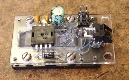
In order to test everything together before committing to a PCB, I laser-cut a mockup from acrylic, to which I hot-melt-glued the components and underneath which I wired the circuit. Acrylic doesn't make a very nice circuit board, BTW. Its low melting point means you really have to work fast with the soldering iron; and heaven help you if you need to use solder wick! But, despite numerous melt "adventures", I got it to work. Here's what the whole initial proto module looks like:
The overall X/Y dimensions are 1.8" x 1.0". The PCB overhangs the base by 1/4" to allow access to the PCB's two mounting holes in the end. You'll notice that the board uses all through-hole components. This is because it will be offered in kit form. Ken and I both agreed that this is the best way to keep costs down and provide the maximum value to the end-user.
Now that I see how everything fits together, I can lay out the PCB and get some protos made. More later!
-Phil
_
Post Edited (Phil Pilgrim (PhiPi)) : 3/9/2010 3:16:26 AM GMT
370 x 298 - 15K
304 x 298 - 13K
500 x 260 - 3K
452 x 281 - 43K
449 x 281 - 45K
Comments
I was looking at a similar circuit design to drive an SHT11 sensor from two wires instead of the 4 necessary by using a 3.3v/5v split design. When 5v is applied to the two wires, it charges a cap on the SHT11 board. When less than 5v is seen on the two wires, the SHT11 works as if it's connected to the data and clock lines. The SHT11 draws such little current that I believe it's feasible to power it from a cap while it takes a measurement and sends out the reading.
▔▔▔▔▔▔▔▔▔▔▔▔▔▔▔▔▔▔▔▔▔▔▔▔
Andrew Williams
WBA Consulting
WBA-TH1M Sensirion SHT11 Module
Special Olympics Polar Bear Plunge, Mar 20, 2010
Propeller-Based Reverse Geo-Cache Birthday Present Project
Post Edited (WBA Consulting) : 2/7/2010 12:33:32 AM GMT
-Phil
I had to cut them out with the CNC mill. This is what the mouse sensor board looks like before assembly:
... and after assembly:
So far, things seem to work okay...
-Phil
What type of info does the sensor provide ?
Is it image data ? Or movement data ? Or something else ?
Detail man....We want details... [noparse];)[/noparse]
Bean
▔▔▔▔▔▔▔▔▔▔▔▔▔▔▔▔▔▔▔▔▔▔▔▔
- - - - - - - - - - - - - - - - - - - - - - - - - - - - - - -
Use BASIC on the Propeller with the speed of assembly language.
PropBASIC thread http://forums.parallax.com/showthread.php?p=867134
March 2010 Nuts and Volts article·http://www.parallax.com/Portals/0/Downloads/docs/cols/nv/prop/col/nvp5.pdf
·
-Phil
dX-dY is great.
The image data would probably be of very little practical use anyway.
Bean.
▔▔▔▔▔▔▔▔▔▔▔▔▔▔▔▔▔▔▔▔▔▔▔▔
- - - - - - - - - - - - - - - - - - - - - - - - - - - - - - -
Use BASIC on the Propeller with the speed of assembly language.
PropBASIC thread http://forums.parallax.com/showthread.php?p=867134
March 2010 Nuts and Volts article·http://www.parallax.com/Portals/0/Downloads/docs/cols/nv/prop/col/nvp5.pdf
·
I wanted a way for users to see their Mouse Sensor in action graphically, so I wrote a Perl program that tracks the sensor's motion on the screen. Here's what the output looks like:
From this program I learned that it's difficult for the BASIC Stamp to keep up with motion at 800 dpi without overflow occurring in the 8-bit DX and DY registers. So I changed the resolution in the default PBASIC demo program to 400 dpi. It tracks much better now. With a Propeller, of course, this would not be an issue.
One thing that users will have to be aware of is that this is a mouse sensor, not an XY encoder. It's very good at measuring relative motion, but its repeatability in an absolute sense is not perfect. After all, it's optimized to track on just about any random surface, not one with encoder stripes. To illustrate what I mean, place your computer mouse at a known location on the mousepad, so the mouse pointer is near the middle of the screen. Touch your finger to the screen at the mouse pointer's location, then move the mouse around a bit, and return it to its beginning locaton on the mousepad. Is the mouse pointer under your finger? Probably not.
Now I've got to come up with a Propeller object for this thing and do the docs. More later!
-Phil
Post Edited (Phil Pilgrim (PhiPi)) : 2/23/2010 4:15:45 AM GMT
At the risk of sounding really stupid here, other than its' cool, why do I want this? There is already an optical mouse that interfaces nicely with the propeller. At least I am guessing it does since the ps2 plug is there for it to attach to ( haven't tried it yet ).
▔▔▔▔▔▔▔▔▔▔▔▔▔▔▔▔▔▔▔▔▔▔▔▔
- Stephen
Think of this item not a a mouse replacement, but has an encoder and feedback mechanism.
▔▔▔▔▔▔▔▔▔▔▔▔▔▔▔▔▔▔▔▔▔▔▔▔
Timothy D. Swieter, E.I.
www.brilldea.com - Prop Blade, LED Painter, RGB LEDs, 3.0" LCD Composite video display, eProto for SunSPOT
www.tdswieter.com
-Phil
I was just wondering if it was something like the new relay board or a gps where there was an obvious use.· Sounds like this is more like some of the other sensors that are there to tweak the immagination.· Those are fun to expiriment with.· Now I'm going to have to think of a fun way to use it.
Thanks
Reason #1: Because it's another unique sensor with Parallax support (courtesy of Phil) and code examples for BASIC Stamp and Propellers. Did you see the Mouse Monitor program above to help you visualize the output?
Reason #2: It's not stuck in a standard mouse package designed for the palm of your hand - giving you the chance to use it for other kinds of unique applications of your choice. Hmm. Think it could be feedback for a robot or a position control device for manufacturing?
Reason #3: DIY interest - all through-hole design means you get to build it! You will know how it functions and be proud of your soldering work.
Reason #4: Experimentation and innovation. You aren't buying toilet bowl brushes from us, but interesting tools that develop your innovative and creative interests. Investing in yourself! We have a mission statement about serving innovative and "naturally curious" people. That's you!
Reason #5: Cost! Okay, this is certainly one of those devices that costs more in this form than it does in the native mouse design. But it'll still be under $20.
Reason #6: Education and open-source. We'll give you the whole project, from schematic, BOM to gerbers and code. . . for free and without restriction.
Ken Gracey
Parallax Inc.
And gosh, Phil, if it's not a brain child then from what part of you has it been begat?
Post Edited (ElectricAye) : 2/23/2010 5:02:52 AM GMT
-Phil
Post Edited (Phil Pilgrim (PhiPi)) : 2/23/2010 5:38:15 AM GMT
-Phil
_
Post Edited (Phil Pilgrim (PhiPi)) : 2/25/2010 9:17:18 PM GMT
I'm thinking liquid turbulence detector, aren't you?
When will this sensor be available for sale?
Me:
1. Write a Propeller object.
2. Finish the docs.
3. Submit protos and docs for Parallax tech and editorial reviews. If necessary, make revisions per the reviews.
4. Order the first batch of boards.
5. Make the first batch of bases.
Parallax:
6. Create inventory items and purchase components from my bill of materials.
7. Kit the parts in bags and label.
8. Take photos.
9. Set pricing.
10. Create a product page.
11. Inform distributors.
12. Announce it to the world.
Okay, there's still a lot to do yet, and I probably missed a step or two.
-Phil
Phil is at Step #3 and Parallax is at Step #6, meaning we're within weeks at this stage.
Had a chance to do an early review on the documentation this morning and this kit is fun, easy to use and rewarding to build.
Maybe Phil will post the draft documents here.
▔▔▔▔▔▔▔▔▔▔▔▔▔▔▔▔▔▔▔▔▔▔▔▔
Ken Gracey
Parallax Inc.
Follow me at http://twitter.com/ParallaxKen for some insider news.
-Phil
This device has a lot of potential. But it seems to me that this "Sensor" forum doesn't get much traffic, so perhaps you should also make the announcement in the Propeller Forum and Stamp forums, too, so the great unwashed masses of those forums can get interested, too.
▔▔▔▔▔▔▔▔▔▔▔▔▔▔▔▔▔▔▔▔▔▔▔▔
"When the government is afraid of the people there is liberty, when the people are afraid of the government, there is tryanny"
· Thomas Jefferson
·
▔▔▔▔▔▔▔▔▔▔▔▔▔▔▔▔▔▔▔▔▔▔▔▔
The smarter I get, the more I understand I don't know!
▔▔▔▔▔▔▔▔▔▔▔▔▔▔▔▔▔▔▔▔▔▔▔▔
Ken Gracey
Parallax Inc.
Follow me at http://twitter.com/ParallaxKen for some insider news.