

Trying to get camera working with my propeller setup, need some input
 charleyshf
Posts: 165
charleyshf
Posts: 165
Hello,
For the past week I have been trying to duplicate what Hanno has done in the article from last year in Circuit Cellar Magazine. The link to it is here·.·I am using all the same hardware. Attached is the schematic I am working with.
I have soldered a total of 4 ADC08100 A/D chips to TSSOP to DIP adapters, all have tested good. I have tried this with the gadget gangster propeller platform module(2 of them), I have also tried it with the Parallax protoboards as well.
I have tried all sorts of different wiring(different sizes as well)·thinking it might be·some sort of ground problem or·analog noise issue, but·I have not been able to come up with a solution.·All connections are short as possible.
I have been emailing back and fourth with Hanno on this, but we are both at a loss at this point.
Using viewport I can get a display, however the quality is too low, not even useable for any app.
I have also tried 3 different CCam2-a modules, all new.
I have also tried separate power supplys, a different computer, different usb cables, and even re-installed viewport. I am looking for any ideas at this point.
Thank You
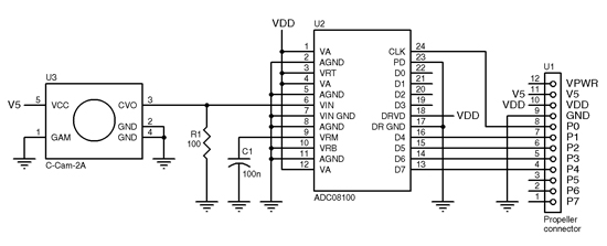
550 x 223 - 56K
Comments
- replace the 100R resistor with 75R
- add a 100nF decoupling cap between any Vdd pin and nearest GND
- put a scope on the camera output and make sure you are getting enough voltage swing
- try feeding the video out to a TV and see if you get a decent image
- make sure there is enough light on whatever you are trying to image
▔▔▔▔▔▔▔▔▔▔▔▔▔▔▔▔▔▔▔▔▔▔▔▔
www.mikronauts.com E-mail: mikronauts _at_ gmail _dot_ com 5.0" VGA LCD in stock!
Morpheus dual Prop SBC w/ 512KB kit $119.95, Mem+2MB memory/IO kit $89.95, both kits $189.95 SerPlug $9.95
Propteus and Proteus for Propeller prototyping 6.250MHz custom Crystals run Propellers at 100MHz
Las - Large model assembler Largos - upcoming nano operating system
I attached a picture to show what kind of video I am getting with this setup.
The edges on your image look nice and sharp, but the brightness looks screwy (kinda like you might get if you flipped a pair of data lines from the ADC)
Download/Print a set of Greyscale bars something like this www.mediacollege.com/video/test-patterns/grayscale.html and see what your results look like.
▔▔▔▔▔▔▔▔▔▔▔▔▔▔▔▔▔▔▔▔▔▔▔▔
Life may be "too short", but it's the longest thing we ever do.
Thank you for the link.
I downloaded that grayscale chart, and it looks like something is backwards, I'm going to go through the wiring again..
ADC08100 Pins --> Propeller Pins
Pin24(CLK) Pin8(P8)
Pin23 (GROUND)
Pin22 NC
Pin21 NC
Pin20 NC
Pin19 NC
Pin18 VDD(+3VDC)
Pin17 GROUND
Pin16 (D4) Pin7(P7)
Pin15 (D5) Pin6(P6)
Pin14 (D6) Pin5(P5)
Pin13 (MSB) Pin4(P4)
You have connected the MSB of the ADC to the LSB of the prop... and so on...
▔▔▔▔▔▔▔▔▔▔▔▔▔▔▔▔▔▔▔▔▔▔▔▔
Life may be "too short", but it's the longest thing we ever do.
The diagram is a little confusing,· I had emailed Hanno about the·diagram and he verified that my current pin connections are correct, the P0-P7 he has on that diagram are not the actual Propeller pins, rather it's a custom connector he had made for his dancebot. Hanno has a couple different version of his code out there, and the one I am using comes with the most recent version of viewport, here is a snippet of code that shows where the pins connect:
''change the first two constants to match where your adc input/output are
· VIDEOSTART=4··· ''pins VIDEOSTART..VIDEOSTART+3 should connect to the 4MSB of the ADC
· ADC_CLOCK_PIN=8 ''pin ADC_CLOCK_PIN should connect to your ADC's clock·
·
VIDEOSTART=4 ''pins VIDEOSTART..VIDEOSTART+3 should connect to the 4MSB of the ADC
To me, the 4MSB of an 8 bit ADC is D4/D5/D6/D7
If you are using that in a nybble configuration to a propeller, it would make sense to have the "most" LSB, of the ADC, connected to the "most" LSB of the Propeller Nybble you are connecting to. Your connections still look backwards to me. Then again, I guess at least you are getting sync.
▔▔▔▔▔▔▔▔▔▔▔▔▔▔▔▔▔▔▔▔▔▔▔▔
Life may be "too short", but it's the longest thing we ever do.
I will like to try this also, i have a PCB done for this diagram.
Now if I can just remember what I was going to do next .............
·
From what I have now, where the camera is working
ADC08100 Pins --> Propeller Pins
Pin24(CLK) Pin8(P8)
Pin23 (GROUND)
Pin22 NC
Pin21 NC
Pin20 NC
Pin19 NC
Pin18 VDD(+3VDC)
Pin17 GROUND
Pin16 (D4) Pin4(P4)
Pin15 (D5) Pin5(P5)
Pin14 (D6) Pin6(P6)
Pin13 (D7 MSB) Pin7(P7)
thanks
Post Edited (charleyshf) : 2/5/2010 5:51:36 PM GMT
Can you post some screenshots so we can see the quality?
▔▔▔▔▔▔▔▔▔▔▔▔▔▔▔▔▔▔▔▔▔▔▔▔
www.mikronauts.com E-mail: mikronauts _at_ gmail _dot_ com 5.0" VGA LCD in stock!
Morpheus dual Prop SBC w/ 512KB kit $119.95, Mem+2MB memory/IO kit $89.95, both kits $189.95 SerPlug $9.95
Propteus and Proteus for Propeller prototyping 6.250MHz custom Crystals run Propellers at 100MHz
Las - Large model assembler Largos - upcoming nano operating system
You will just have to pay for shipping, but i think it will go fine if i am sending it to you in a letter. I am in Romania.
That is actually quite good considering it is only 16 level gray scale!
(and you are most welcome)
▔▔▔▔▔▔▔▔▔▔▔▔▔▔▔▔▔▔▔▔▔▔▔▔
www.mikronauts.com E-mail: mikronauts _at_ gmail _dot_ com 5.0" VGA LCD in stock!
Morpheus dual Prop SBC w/ 512KB kit $119.95, Mem+2MB memory/IO kit $89.95, both kits $189.95 SerPlug $9.95
Propteus and Proteus for Propeller prototyping 6.250MHz custom Crystals run Propellers at 100MHz
Las - Large model assembler Largos - upcoming nano operating system
Bill, I too was amazed by the image quality when I first saw it- remember that this is from a tiny, camera available here.- and it's video! At 2mbps you get ~10 frames/second.
The site also sells also cheaper, $6 cameras...
Now, try out the "face tracking" feature from OpenCV- it's integrated into ViewPort!
Hanno
▔▔▔▔▔▔▔▔▔▔▔▔▔▔▔▔▔▔▔▔▔▔▔▔
Co-author of the official Propeller Guide- available at Amazon
Developer of ViewPort, the premier visual debugger for the Propeller (read the review here, thread here),
12Blocks, the block-based programming environment (thread here)
and PropScope, the multi-function USB oscilloscope/function generator/logic analyzer
P.S. Thank you, BradC.
These guys are GREAT!! I was starting to worry you weren't going to email me back anymore with all the problems I had!!!
After working on this for over a week and getting help to get it going I had to sit back and actually try to remember why I started working on this... ·That would be my bot that is in a box in parts still waiting for me to put it together!
Thanks again everyone!!
·
But I think the Propeller Pinout on page 260 is in error. Take for example Pin 40 (called P15). On the DIP package, this would be P31. On the LQFD, it would be VDD. They just don't match up.
Unless these are referring to nomenclature on a board that has nothing to do with the Propeller pinout, in which case it might be a little confusing.
Jim
Granted I have not read both chapters completley through yet so I may be talking out of turn, I am just saying it looks a little confusing to the casual observer.
I know Hanno will chime in a straighten this out. He has never let us down before with his great products and projects.
Jim
▔▔▔▔▔▔▔▔▔▔▔▔▔▔▔▔▔▔▔▔▔▔▔▔
Life may be "too short", but it's the longest thing we ever do.
I apologize for not being consistent across my projects. I have multiple implementation of the vision grabber hardware- one on the DanceBot (which uses pins 19..23 and 24 as clock) and another using the IODreamkit (pins 4..7 and 8 as clock). ViewPort's "PropCVCapture.spin" object let's you define which pins to monitor using the "VIDEOSTART" constant. I currently default this to 4- meaning the ADC's output should be on pins 4,5,6,7- with 7 being the most significant bit of the ADC. Pin 8 is used to provide a clock to the ADC. This is what's shown in Chapter 7. The video capture algorithm only captures those 4 bits, but if you want you can connect the lower 4 bits as well and use program #9 as an oscilloscope.
Amazing the video synched at all!
Hanno
▔▔▔▔▔▔▔▔▔▔▔▔▔▔▔▔▔▔▔▔▔▔▔▔
Co-author of the official Propeller Guide- available at Amazon
Developer of ViewPort, the premier visual debugger for the Propeller (read the review here, thread here),
12Blocks, the block-based programming environment (thread here)
and PropScope, the multi-function USB oscilloscope/function generator/logic analyzer
Actually what I was working on was from a link from an article I·was wokring on·from last year, in the new book I posted in this thread here:
http://forums.parallax.com/showthread.php?p=877819
Just waiting for them to confirm it.
Jim
"What i am interested to know is: what if i use a very high quality camera, also B/W model, but with a much much better image?"
▔▔▔▔▔▔▔▔▔▔▔▔▔▔▔▔▔▔▔▔▔▔▔▔
www.mikronauts.com E-mail: mikronauts _at_ gmail _dot_ com 5.0" VGA LCD in stock!
Morpheus dual Prop SBC w/ 512KB kit $119.95, Mem+2MB memory/IO kit $89.95, both kits $189.95 SerPlug $9.95
Propteus and Proteus for Propeller prototyping 6.250MHz custom Crystals run Propellers at 100MHz
Las - Large model assembler Largos - upcoming nano operating system