

Enclosure for Propeller Demo Board
 Phil Pilgrim (PhiPi)
Posts: 23,514
Phil Pilgrim (PhiPi)
Posts: 23,514
The Propeller Demo Board is full-featured enough that it could find ahome in many end applications — if it only had a decent enclosure. The board doesn't have any mounting holes, and neither the on-off switch, the power LED, nor the A16-A23 LEDs are board-edge accessible. If a board isn't designed around a particular enclosure, finding one after the fact can be a challenge.
I had a scrap piece of extrusion lying around (Lansing Micro-Pak DQ0), which was too wide for the board (better than too narrow!) and long enough that I could cut it to the Demo Board's 3.01" (including the VGA connector's slight overhang) length. Then I designed some laser-cut acrylic parts to hold the board in place inside the extrusion, along with laserable laminate end panels having cutouts for the connectors.
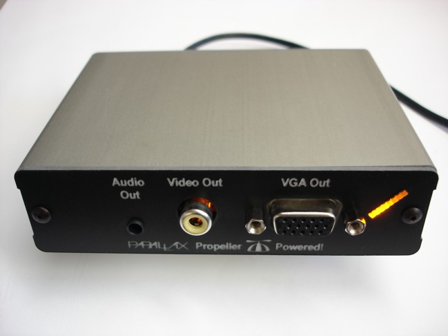
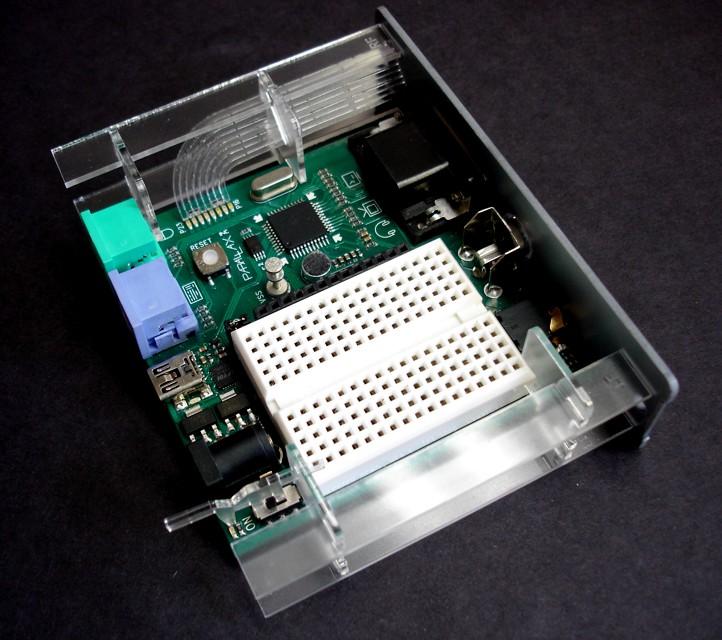
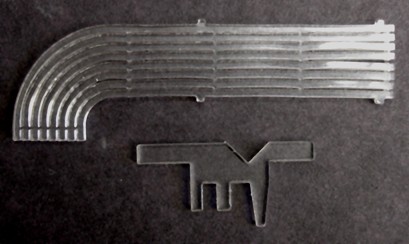
I was tempted to add a separate on/off switch, but I didn't want to make any modifications at all to the Demo Board. It occurred to me that a piece of acrylic could be crafted to grab the switch slider and protrude from the rear panel in a pull on/push off fashion. It also occurred to me that the same piece of acrylic could be used to direct the light from the LED to the end of the panel protrusion when the board is turned on. The "lightpipe" view below shows the switch/LED gizmo, the "innards" view shows it in place, and the "rear" view shows it in action.
I was going to call it quits at this point, but those eight amber LEDs gnawed at me. I figured that if the acrylic worked as a light pipe over a short distance, it might work just as well over a longer one. So I designed the bigger one shown in the "lightpipe" photo and shown installed in the "innards" photo. I had to connect the eight individual pipes together at intervals just to keep them unitized so they wouldn't flop around like spaghetti. This results in a little bit of optical crosstalk between adjacent pipes. As a consequence, the resulting panel display's utility as eight individual status lights might be limited. But it's great for things like graphical level meters.
Anyway, I don't know what I want to do with this now that I have it. But it was fun solving the problems encountered along the way. I suppose, if there were adequate demand, I could make more of them.
-Phil
_
I had a scrap piece of extrusion lying around (Lansing Micro-Pak DQ0), which was too wide for the board (better than too narrow!) and long enough that I could cut it to the Demo Board's 3.01" (including the VGA connector's slight overhang) length. Then I designed some laser-cut acrylic parts to hold the board in place inside the extrusion, along with laserable laminate end panels having cutouts for the connectors.
I was tempted to add a separate on/off switch, but I didn't want to make any modifications at all to the Demo Board. It occurred to me that a piece of acrylic could be crafted to grab the switch slider and protrude from the rear panel in a pull on/push off fashion. It also occurred to me that the same piece of acrylic could be used to direct the light from the LED to the end of the panel protrusion when the board is turned on. The "lightpipe" view below shows the switch/LED gizmo, the "innards" view shows it in place, and the "rear" view shows it in action.
I was going to call it quits at this point, but those eight amber LEDs gnawed at me. I figured that if the acrylic worked as a light pipe over a short distance, it might work just as well over a longer one. So I designed the bigger one shown in the "lightpipe" photo and shown installed in the "innards" photo. I had to connect the eight individual pipes together at intervals just to keep them unitized so they wouldn't flop around like spaghetti. This results in a little bit of optical crosstalk between adjacent pipes. As a consequence, the resulting panel display's utility as eight individual status lights might be limited. But it's great for things like graphical level meters.
Anyway, I don't know what I want to do with this now that I have it. But it was fun solving the problems encountered along the way. I suppose, if there were adequate demand, I could make more of them.
-Phil
_
648 x 486 - 44K
648 x 486 - 42K
722 x 640 - 132K
409 x 244 - 36K
Comments
I wish I had your mechanical skills and workshop.
▔▔▔▔▔▔▔▔▔▔▔▔▔▔▔▔▔▔▔▔▔▔▔▔
www.mikronauts.com E-mail: mikronauts _at_ gmail _dot_ com 5.0" VGA LCD in stock!
Morpheus dual Prop SBC w/ 512KB kit $119.95, Mem+2MB memory/IO kit $89.95, both kits $189.95 SerPlug $9.95
Propteus and Proteus for Propeller prototyping 6.250MHz custom Crystals run Propellers at 100MHz
Las - Large model assembler Largos - upcoming nano operating system
What I've seen done for "multi-conductor" light pipes, is a separate piece of black plastic used as "stringers" to tie the various pieces together. This eliminates/minimizes the cross talk.
▔▔▔▔▔▔▔▔▔▔▔▔▔▔▔▔▔▔▔▔▔▔▔▔
John R.
Click here to see my Nomad Build Log
The lightpipes are actually quite a simple concept although trial and error is often needed. Sometimes it is better to use a straight lightpipe and add a 90 degree bend with a 45 degree angle to cause the light to be reflected. I used lightpipes in my modems in the 90's. It took a bit of filing to·find the best method. I used seperate fingers to pick up the leds and the fingers were only joined at the outer surface. This ensured no bleed between the leds. BTW, I used superbright smt LEDs (of the day) and 3K3 resistors to 5V giving 1mA per LED.
I will look for my lightpipes and post a photo here later.
▔▔▔▔▔▔▔▔▔▔▔▔▔▔▔▔▔▔▔▔▔▔▔▔
Links to other interesting threads:
· Home of the MultiBladeProps: TriBlade,·RamBlade,·SixBlade, website
· Single Board Computer:·3 Propeller ICs·and a·TriBladeProp board (ZiCog Z80 Emulator)
· Prop Tools under Development or Completed (Index)
· Emulators: CPUs Z80 etc; Micros Altair etc;· Terminals·VT100 etc; (Index) ZiCog (Z80) , MoCog (6809)·
· Prop OS: SphinxOS·, PropDos , PropCmd··· Search the Propeller forums·(uses advanced Google search)
My cruising website is: ·www.bluemagic.biz·· MultiBlade Props: www.cluso.bluemagic.biz
▔▔▔▔▔▔▔▔▔▔▔▔▔▔▔▔▔▔▔▔▔▔▔▔
There is no problem that can't be solved with a suitable amount of explosives!
EOD Memorial
-Phil
Very nice job.
What would be the cost for one or more ?
Bean
▔▔▔▔▔▔▔▔▔▔▔▔▔▔▔▔▔▔▔▔▔▔▔▔
- - - - - - - - - - - - - - - - - - - - - - - - - - - - - - -
Use BASIC on the Propeller with the speed of assembly language.
PropBASIC thread http://forums.parallax.com/showthread.php?p=867134·
Looks like you've also managed to label the clear parts "RF" etc on a lower power setting.
cheers
tubular
Probably kinda steep. Lansing's price on their standard extrusion lengths runs about $17-$20. So I'd have to buy probably 50 custom cut ones to get that price. The acrylic isn't all that expensive, but there's time on the machine to cut and engrave it. I'll see how much interest I get and go from there.
2D with Corel Draw. And a lot of time spent with calipers, measuring the PCB and its part locations. Oh, and a lot of trial and error after the fact.
Yes: RF = Right Front; LF = Left Front. It makes assembly simpler — even for the guy who designed it!
-Phil
Post Edited (Phil Pilgrim (PhiPi)) : 1/30/2010 3:20:30 AM GMT
Bill
I want a few if you go into production BTW.
▔▔▔▔▔▔▔▔▔▔▔▔▔▔▔▔▔▔▔▔▔▔▔▔
Signature space for rent!
Send $1 to CannibalRobotics.com.
does this mean you got a laser-scanner with enough power to cut plastic?
I worked in a company that manufactured laser-scanners to mark and cut special foils. They use High-power-laserdiodes to pump a YAG-laser which resulted in
an optical power of 30W. This was not really enough to cut bigger plastics than the foils with 0.5mm. So how much power does your laser have?
best regards
Stefan
Awesome case! How about moving the breadboard to the top?
OBC
▔▔▔▔▔▔▔▔▔▔▔▔▔▔▔▔▔▔▔▔▔▔▔▔
New to the Propeller?
Visit the: The Propeller Pages @ Warranty Void.
Yes, 35W CO2 laser (Epilog Zing). It will cut through up to 1/4" acrylic in one pass.
The idea is to house and protect a finished product, once any breadboarding is complete. There's room on the left side of the front panel for a connector that can interface to some internal breadboarded circuitry, if necssary.
-Phil
Post Edited (Phil Pilgrim (PhiPi)) : 1/30/2010 7:40:21 PM GMT
Makes me want to finish up my DIY CNC mill!
Rick
▔▔▔▔▔▔▔▔▔▔▔▔▔▔▔▔▔▔▔▔▔▔▔▔
PrEditor·- Text Editor
NYC Area Prop Club
·
Doug
▔▔▔▔▔▔▔▔▔▔▔▔▔▔▔▔▔▔▔▔▔▔▔▔
Style and grace : Nil point
I love it when you gurus show what you can do. This light pipe thing is especially awesome.
thanks for sharing!
I have my demoboard in a Polycase plastic enclosure and had to enlarge the USB opening to make room for the connector molding to fit through so it actually looks like I messed it up. The holes on mine are overlapping the base and lid, so that's another downfall. The board is only secured in by friction. My setup does work good enough for me though (aka: it already survived a drop
One of my Propeller Contest Entries is a full Propeller Development PCB that fits into a case that works well as a handheld or desktop enclosure. I may have to have you do the end panel!
▔▔▔▔▔▔▔▔▔▔▔▔▔▔▔▔▔▔▔▔▔▔▔▔
Andrew Williams
WBA Consulting
WBA-TH1M Sensirion SHT11 Module
Special Olympics Polar Bear Plunge, Mar 20, 2010
Propeller-Based Reverse Geo-Cache Birthday Present Project
Post Edited (WBA Consulting) : 2/2/2010 1:03:46 AM GMT
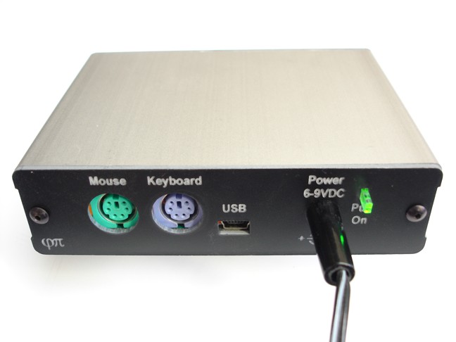
The USB connector on my Demo board extends over the edge just a hair, and the panel is only 1/16" thick. The molding on a standard USB connector fits snug against the panel, but it's inserted all the way. IOW it just makes it.
It's interesting to note that the mouse and keyboard connectors are designed to hang over the edge; but they don't, since they're too far back on the board. As a consequence, they tilt upwards a little, and the bottom of the connector housing is pinched inwards a bit from the extra pressure. These connectors would work better with an overhang and a rectangular panel opening, but they're also fine the way they are.
-Phil
▔▔▔▔▔▔▔▔▔▔▔▔▔▔▔▔▔▔▔▔▔▔▔▔
MOORE'S LAW: The capabilities of electronics shall double every 18 months.
cloyd's corollary: Hardware is easy, software is hard.