

Help to make a keyboard to PSK31 mode of modulation and decode
 lcyepiz
Posts: 26
lcyepiz
Posts: 26
The pks31 was invented by Peter Martinez
The wide band to transmit data is only few hertz maybe 30hz or less
This form of modulation is used by ham in the around world
They use a computer to modulate and decode the signal PSK31,
the plataform is in windows or linux, but to carry to field event
the computer plus the radio and antenna is a lot of stuff
some time the computer is bigger than the radio so i trying to reduce
the weight in the field.
My goal is·make a propeller psk31 station.
The first·step to generate the signal and the second part is decode this signal.
To transmit data·generate a sine signal·like 1khz ·(to be used to modulate RF in SSB mode)
The data is encoded by a varicode table like this:
A·· 1111101
B·· 11101011
C·· 10101101
D·· 10110101
E·· 1110111
F·· 11011011
G·· 11111101
H·· 101010101
I·· 1111111
J·· 111111101
K·· 101111101
L·· 11010111
M·· 10111011
N·· 11011101
You can view the full varicode and theory a:
http://aintel.bi.ehu.es/psk31theory.html
A each change from 1 to 0 the·sine signal decrement the level to zero·and increment the level·but a·phase reversal
view a example beacom (report a station a fixed time to check propagation and other stuff)
http://www.njqrp.org/digitalhomebrewing/psk31beacon/beacon_source.html
thanks a lot
XE2NBW
Luis C. Yepiz
366 x 253 - 17K
213 x 60 - 2K
Comments
I'm very interested in your project. I would also like a small, microprocessor-based QRP station. I'll be happy to help with testing, etc.
73,
Michael KD4SGN
What bands do you use PSK31 on? Does it have the same FCC limitations as packet in the us?
Thanks
Doug
At least have a look at the PDF (in the zip file) because he did an excellent job on the documentation.
The forum entry is here: http://forums.parallax.com/showthread.php?p=789451
Post Edited (hinv) : 1/17/2010 7:04:36 AM GMT
-Phil
AD7YF
I've just given Leon a call: he's a Ham too and knows all about PSK31!
T o n y
I could probably help with testing, QRM permitting.
73, Leon
▔▔▔▔▔▔▔▔▔▔▔▔▔▔▔▔▔▔▔▔▔▔▔▔
Amateur radio callsign: G1HSM
Post Edited (Leon) : 1/17/2010 12:36:03 PM GMT
The FFT is needed to show all the signals on the band AND to phase demodulate a chosen signal.
Propeller can use the 136KHZ LOWFR BAND, 160 METERS, 80 METERS
and for the hams with TECH license, with a NE602, push up the 4MHZ NCO to 50-54 MHZ (6 METERS) with 49.86Mhz crystal (very common here).
You can probably replace the FFT with a sweep, and a separate cog to demodulate the chosen signal.
Transmitting PSK31 is easy, just keep flipping a CW upside down everytime a bit changes.
Also, remember the Propeller AM radio thread, it may be useful for this.
▔▔▔▔▔▔▔▔▔▔▔▔▔▔▔▔▔▔▔▔▔▔▔▔
VIRAND, If you spent as much time SPINNING as you do Trolling the Forums,
you'd have tons of awesome code to post! (Note to self)
It's quite a big application - about 9k. There are some large tables involved.
Implementing reception first would be advisable, as that's the hardest bit, and testing is easy.
Leon
▔▔▔▔▔▔▔▔▔▔▔▔▔▔▔▔▔▔▔▔▔▔▔▔
Amateur radio callsign: G1HSM
Post Edited (Leon) : 1/17/2010 1:29:39 PM GMT
For develop testing i use the winpsk you can downlaod a free from
http://www.moetronix.com/ae4jy/winpsk.htm
this a sofware of AE4Jy
My test hardware is the propeller demo board , i send the audio of PSK31
to mic input of the computer, today i can not view character in the WINPSK
A start phase of this program you not need a HF radio, i making some advanced
but dont work , when have a working program i upload to the fourum,
my first target is generate the audio PSK31 send to mic input of computer running WINPSK
and see the character in the program.
The next step in the program is decode the signal PSK31 of the audio sending from
the PC running WINPSK to propeller demo board, but first the first the encode of PSK31
thanks a lot for yours answers
Luis C Yepiz
XE2NBW
even if you are sending null data between characters.
▔▔▔▔▔▔▔▔▔▔▔▔▔▔▔▔▔▔▔▔▔▔▔▔
VIRAND, If you spent as much time SPINNING as you do Trolling the Forums,
you'd have tons of awesome code to post! (Note to self)
-Phil
A end of each message the PSK31 signal stop.
for send a mesage need to group each letter with the varicode and send
each bit, a end of message the PSK31 turn off for reception.
This PSK31 mode work open and dont have any conection to other station
This modulation of signal PSK31 is half duplex, and dont have conection to RX-TX or TX-RX
only send a one way an get any character in another way
Dont have any threatment of error or conection of stations,
this work like a chat over RF to comunicate with other people.
This comunicattion is like CW(MORSE):
By example Station1 and station2
The station1(Me) start searching to comunicate.
Station1
CQ CQ CQ DX XE2NBW
CQ->Code to call a one station 3 times a convention from CW comunnication
DX-> To other station a distance
XE2NBW My call sign in Mexico
The varicode of PSK31 is
10101101,111011101,1 CQ ", " for view the start and end of each character
10101101,111011101,1 CQ "1" is a space
10101101,111011101,1 CQ
101110101,1110111,11101101,11011101,11101011,10101110,1 XE2NBW
look if send a pure tone it is the varicode for SPACE.
The program generate a bit-bit FIFO from varicode an feed to modulator
First bit to Tx >1010110111101110111010110111101110111010110111101110111011101011
110111111011011101110111101011101011101<-Last bit to TX
"The bits constituting the Varicode character being sequentially presented for modulation are
inspected on a bit-by-bit basis at each 31ms bit processing window. When a "1" is encountered,
nothing is done in that window. The sine wave construction continues
However when a "0" is encountered, the rules of PSK31 modulation state that a phase reversal
must be forced in signal"
In another words start signal by example 1000hz (if selected this),when found
the next bit is 1 continue the same signal 1000hz a max level, but if the feeder of bit found
a 0, the modulator need to decrement the level of signal to ZERO, and start again 1000hz
signal but a phase reversal and increment the level to maximo posible.
if any station receive my call
Maybe send to me:
CQ W6TY TU XE2NBW
if I receive this the PARTY start, so the remote station and the station1 chat whatever!
I hope it is usefuly
Luis C. Yepiz
XE2NBW
What I was wondering, though, is that if one is a slow typist, what happens in the intervals between letters? Are they filled with something (i.e. NULs), or does modulation (and thus the RF in SSB) cease entirely? In FSK, there's always a carrier when in transmit mode, regardless of how slowly one is typing. Hence my question.
Thanks,
-Phil
The software for PSK31 i tested have two forms:
A) I can type the message and the final press F12 (WinPSK) to send the full message a one time.
the next letter with a space or 2 to syncro the receiver The varicode for space is 1, start the modulation
a pure tone (1000hz) for 2 time windows of 31ms that is the syncro for next character the receiver
can decode.
Luis C. Yepiz
XE2NBW
-Phil
Its already been done with a dsPIC by George Heron, N2APB, and Milt Cram, W8NUE. See www.nue-psk.com. I have one of the units and it does quite well.
cheers ... BBR
▔▔▔▔▔▔▔▔▔▔▔▔▔▔▔▔▔▔▔▔▔▔▔▔
cheers ... brian riley, n1bq, underhill center, vermont
The Shoppe at Wulfden
www.wulfden.org/TheShoppe/
I now understand your question
The form to detect one character of other is by transmit a especial code 00
this varicode never ocurr inter characters, my before post for the A) and
A) if send a full message send 00 or more 0 inter character
next character.
Correction to bit include character 00 from PSK31 theory.
Station1
CQ CQ CQ DX XE2NBW
CQ->Code to call a one station 3 times a convention from CW comunnication
DX-> To other station a distance
XE2NBW My call sign in Mexico
The varicode of PSK31 is
00,10101101,111011101,00,1 CQ ", " for view the start and end of each character
00,10101101,111011101,00,1 CQ "1" is a space
00,10101101,111011101,00,1 CQ
00,101110101,00,1110111,00,11101101,00,11011101,00,11101011,00,10101110,00,1 XE2NBW
First bit to Tx >001010110111101110100100101011011110111010010010101101111011101001
001011101010011101110011101101001101110100111010110010101110001<-Last bit to TX
Luis C. Yepiz
XE2NBW
The varicode of PSK31 is
00,10101101,00,111011101,00,1 CQ ", " for view the start and end of each character
00,10101101,00,111011101,00,1 CQ "1" is a space
00,10101101,00,111011101,00,1 CQ
00,101110101,00,1110111,00,11101101,00,11011101,00,11101011,00,10101110,00,1 XE2NBW
First bit to Tx >000001010110100111011101001001010110100111011101001001010110100111011101001
001011101010011101110011101101001101110100111010110010101110001<-Last bit to TX
Luis C. Yepiz
XE2NBW
I progress with the modulation of PSK31 but need help
This code generate a sine 1khz modulate·by other sine of 31hz
to pin10 off propeller demo for test
thanks in advanced
loop
                        waitcnt cntacc,cntadd           'wait for cnt sync
                        add     phase_main,freq_main
                        mov     t1,phase_main
                        mov     t2,Modulation_main
                        call    #polar
                        mov     frqa,t1

                        mov     t1,phase_mod
                        call    #getsin
                        mov     Modulation_main,t1
                        DJNZ    phase_mod,#loop
                        mov     phase_mod,C180 'leve zero

'How make a phase inversal in phase_main a this position?


                        jmp     #loop                  'loop
loop_ret                ret

' Get sine/cosine
'
' quadrant: 1 2 3 4
' angle: $0000..$07FF $0800..$0FFF $1000..$17FF $1800..$1FFF
' table index: $0000..$07FF $0800..$0001 $0000..$07FF $0800..$0001
' mirror: +offset -offset +offset -offset
' flip: +sample +sample -sample -sample
'
' on entry: sin[noparse][[/noparse]12..0] holds angle (0° to just under 360°)
' on exit: sin holds signed value ranging from $0000FFFF ('1') to
' $FFFF0001 ('-1')
getcos                  add       t1,sine_180 'for cosine, add 90°
getsin                  test      t1,sine_90 wc 'get quadrant 2|4 into c
                        test      t1,sine_180 wz 'get quadrant 3|4 into nz
                        negc      t1,t1 'if quadrant 2|4, negate offset
                        or        t1,sine_table 'or in sin table address >> 1
                        shl       t1,#1 'shift left to get final word address
                        rdword    t1,t1 'read word sample from $E000 to $F000
                        negnz     t1,t1 'if quadrant 3|4, negate sample
getsin_ret
getcos_ret    RET '39..54 clocks
'
'
' Polar to cartesian
'
'   in:         t1 = 32-bit angle
'               t2 = 16-bit length
'
'   out:        t1 = x|y
polar
                        shr     t1,#32-13               'get 13-bit angle
                        test    t1,sine_180     wz      'get sine quadrant 3|4 into nz
                        test    t1,sine_90      wc      'get sine quadrant 2|4 into c
           if_c         neg     t1,t1                   'if sine quadrant 2|4, negate table offset
                        or      t1,sine_table           'or in sine table address >> 1
                        shl     t1,#1                   'shift left to get final word address
                        rdword  t1,t1                   'read sine/cosine word

                        call    #multiply               'multiply sine/cosine by length to get x|y
                        shr     t1,#1                   'justify x|y integer
                        negnz   t1,t1                   'if sine quadrant 3|4, negate x|y
                        add     t1,msb                  'convert two's complement into duty
polar_ret               ret
sine_90                 long    $0800                   '90° bit
sine_180                long    $1000                   '180° bit
sine_table              long    $E000 >> 1              'sine table address shifted right
msb                     long    $8000_0000              'msb

Sine                    shr     t1,#32-13               'get 13-bit angle
                        test    t1,sine_180     wz      'get sine quadrant 3|4 into nz
                        test    t1,sine_90      wc      'get sine quadrant 2|4 into c
           if_c         neg     t1,t1                   'if sine quadrant 2|4, negate table offset
                        or      t1,sine_table           'or in sine table address >> 1
                        shl     t1,#1                   'shift left to get final word address
                        rdword  t1,t1                   'read sine/cosine word

Sine_ret                ret
'
'
' Multiply
'
'   in:         t1 = 16-bit multiplicand (t1[noparse][[/noparse]31..16] must be 0)
'               t2 = 16-bit multiplier
'
'   out:        t1 = 32-bit product
'
thanks in advanced
I don't see signal output in the code, although I might have missed it.
Realize that you are going to have to use duty cycle modulation or pulse width modulation of squarewaves
through the filters on the audio amp to get the sines out, so consider whether it might work and be easier
to make square waves, or will it be too hard to get rid of the harmonics? It seems to me not too hard, only
maybe needing an extra resistor and capacitor (4 or 5 of them). Maybe use two pins in opposition (differential)
during signal, and both zero output during no transmission, to remove clicks at beginning and end of signal.
I discovered that problem and method when using 2 filtered square waves for DTMF signals.
You ask how to change phase at the zero crossings.
To do that you have to have a whole number of cycles of carrier per modulation period...
1000Hz / 31Hz = ... 32 point something.
It sounds familiar that 32 cycles of 1000 Hz makes a 31.25 Hz or bits per second signal,
so I am sure that what you have to do is start both frequencies at zero phase and they
should be ready for a phase change at zero phase together every 32 cycles, and you
can count 32 cycles of 1KHz to know it is the right time to change modulation phase.
1000Hz = 1ms per cycle
1000Hz/32cycles = 32ms =31.25Hz
1000Hz/31 = 32.2580645161 Hz --- No phase locking possible.
I believe that 31.25Hz is the true timing of PSK31.
if the carrier tone was 1024 then everything would be nice and neat and 32x32=1024
and that would be called PSK32. There must be a good reason why that was not used,
because it might have been simpler. Probably because 1024 is a harmonic of 32,
and PSK32 for some reason wouldn't work as well because of that, and I don't know why.
(It reminds me of the reason for old NTSC frequencies such as 3579545.4545 for color, not 3600000.)
I DON'T THINK THE 31.25 WILL FORCE CALCULATING FRACTIONS, 32 CYCLES of 1000Hz per bit every 32ms is enough.
1000Hz can be divided by 32 easily also, because every 32 cycles, one bit of the cycle count always changes,
right at the time for zero crossing and phase change.
I think you know how to change phase, just flip bits. With sinewaves, flip all bits and then add 1.
▔▔▔▔▔▔▔▔▔▔▔▔▔▔▔▔▔▔▔▔▔▔▔▔
VIRAND, If you spent as much time SPINNING as you do Trolling the Forums,
you'd have tons of awesome code to post! (Note to self)
The output signal is a pin 10, you need a low filter pass like the onboard of the propeller demo board (10k and a cap 10nf) a pin10 or pin 11
left or right microphone before of the amplifier, to get the 1khz sine signal modulate by 31.25hz sine.
The correct speed, please test·whith this change
The loop has a speed of 256_000 by second, so if have a sine output from $0FFF..$0000 (4096) for modulation
(180° to· 0°) for code propuse,·The inverse don affect the signal up and dwn like need, a·half signal 31.25
If ·i have 256000/4096=62.5hz/2= 31.25
and the main frequency with freq_main:=$00ff_ffff, i have 1khz
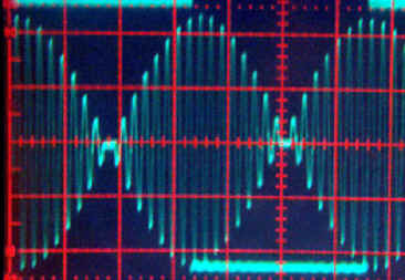
·I test and i·can see in my osciloscope view image.
so, i can not make a phase reversal, in·phase_main·can you help me
thanks a lot
Luis C. Yepiz
XE2NBW
Here is a pdf I found very useful http://det.bi.ehu.es/~jtpjatae/pdf/p31g3plx.pdf
Bean
▔▔▔▔▔▔▔▔▔▔▔▔▔▔▔▔▔▔▔▔▔▔▔▔
- - - - - - - - - - - - - - - - - - - - - - - - - - - - - - -
Use BASIC on the Propeller with the speed of assembly language.
PropBASIC thread http://forums.parallax.com/showthread.php?p=867134·
Before confusing you I need to check them, but I am not sure that the scope is supposed to look like that.
The frequency "long $00ff_ffff" makes no sense to me, did you mean binary $0011_1111?
makes more sense but its 63 which is not useful. You could get 31.25 from 125 by counting to 4 at that rate.
Standby...
▔▔▔▔▔▔▔▔▔▔▔▔▔▔▔▔▔▔▔▔▔▔▔▔
VIRAND, If you spent as much time SPINNING as you do Trolling the Forums,
you'd have tons of awesome code to post! (Note to self)
A simple solution that uses some memory but not too much is synthesis of 4 signals at startup:
#1-Phase 0 of 1Khz: 16 perfect sine cycles of 1Khz
#2-Phase 1 of 1Khz: 16 perfect sine cycles of 1 Khz upside down
and
#3-8 cycles of Phase 0 : 1Khz dropping to zero then rising to former level of phase 1 in next 8 cycles (16 cycles total)
#4-8 cycles of phase 1 : 1Khz dropping to zero then rising to former level of phase 0 in next 8 cycles (16 total)
These last two are made using either half of a 31.25 Hz Cosine wave multiplied by the first two.
Always keep track of the phase.
Start signal with phase 0, sample #1 and send a 1 bit.
To send a 1 bit, continue current phase using one of the first two signals twice.
To send a 0 bit, use the appropriate #3 or #4, then start using the appropriate other #1 or #2 once.
What if I am wrong? It is possible that:
To send a 1 bit, use sample #1 twice
To send a 0 bit, use sample #3 then sample #4
I will figure out which way is right and report back.
To synthesize these signals:
I would use TV and GRAPHICS driver to observe what I synthesized, like a digital scope, just plot the stored signals
as I make them for debugging to make sure they look right.
samples #1 and #2 are 32 sinewaves, one being upside down.
of course the memory could be conserved by using only one sinewave for all 32 and both phases,
but it is just simpler to synth the whole things in memory.
8000 samples per second is plenty, and 256 samples (cool!) make a 31.25 sine, 8 samples make 1000hz sine.
Each of the 4 samples I define therefore fit in 128 bytes at 8-bit sampling (use only top 8 bits of sine)
thats 8 samples per 1000 hz (1ms) sine cycle times 16 which is half of 32 because the phase change
takes that long, the length of half a 31.25hz cosine cycle.
The math for the 31.25 cosine halfcycle phase change is separately signed multiplying it by each of the previously
made 16 cycle 1000 hz phases samples and storing them in their own 128 bytes arrays, after scaling down the
products if necessary. That is where using GRAPHICS as an oscilloscope will be useful for showing how the
well the signals were made. It is convenient to plot 128 points with GRAPHICS.spin
It might be handy to store the arrays below PASM. All of these arrays should fit together in 128 longs.
Now this is enough info for me to start doing this, and write a test beacon for transmit, but I can't promise
to finish it as quickly as possible. I have fldigi to receive with though so I should do it, and then think
about the receiver. The demo board mic should be sufficient for receiving from a tape of what I would
"transmit". When it works it can be cleaned up, but the possibility of QPSK and even morse and hell should
be left open.
▔▔▔▔▔▔▔▔▔▔▔▔▔▔▔▔▔▔▔▔▔▔▔▔
VIRAND, If you spent as much time SPINNING as you do Trolling the Forums,
you'd have tons of awesome code to post! (Note to self)
Channel 1 shows the bit boundaries between 0 and 1. Note that the boundaries are in the middle (the "fat" part) of the modulation envelope sections, not at the ends. Thinking about it this way obviates any need for lookahead when processing characters. The only additional requirement is a call to ramp_up at the beginning of the transmission, and a call to ramp_dn at the end.
'Sorry for the lack of code comments. I'll take care of that later. For now, I've got a social obligation to attend to...
-Phil
Post Edited (Phil Pilgrim (PhiPi)) : 1/23/2010 2:46:50 AM GMT
method of using arrays in DAT sections... as usual none of these work right there... so I will search forums
for working around this spin anomaly again.
BYTE[noparse][[/noparse]index]:=value 'error something else expected for index
BYTE[noparse][[/noparse]ary][noparse][[/noparse]index]:=value 'error something else expected for ary
BYTE[noparse][[/noparse]@index]:=vale 'same error
BYTE[noparse][[/noparse]@@index]:=value 'same error
BYTE[noparse][[/noparse]@ary][noparse][[/noparse]index]:=value 'same error
BYTE[noparse][[/noparse]@@ary][noparse][[/noparse]index]:=value 'same error
ary.BYTE[noparse][[/noparse]index]:= value 'gave up trying combinations, only one way works and not always the same way
simple dumb thing to not be able to do for an hour... looking for the right way for the tenth time now...
I think BST added @@@ operator to force this to just work the obvious way. After all, once index is a
pointer to any byte in hub, byte[noparse][[/noparse]index] just works for any index 0 to 65535. The different sections have
different ways of using labels. Using BYTE[noparse][[/noparse]CON_SECTION_VALUE] works but BYTE[noparse][[/noparse]DAT_SECTION_VALUE]
does not. {shrug} Searching for this common problem and solution.
▔▔▔▔▔▔▔▔▔▔▔▔▔▔▔▔▔▔▔▔▔▔▔▔
VIRAND, If you spent as much time SPINNING as you do Trolling the Forums,
you'd have tons of awesome code to post! (Note to self)
ok, very interesant, you gave to me a another way to make this project
The signal generated in the code i posted has a lot of armonics so,I need
refined or change , so developing continue..........!
I try your way, maybee this way is better.
Thanks a lot
▔▔▔▔▔▔▔▔▔▔▔▔▔▔▔▔▔▔▔▔▔▔▔▔
Juramento YAQUI.
Para ti no habr
The·table is the best option!· I agree
I can see the potential·use of table.
Now, i·understand, the speed for this a modulation is fast and
easy to make, your code·has the way of the modulator PSK31
thanks a lot
▔▔▔▔▔▔▔▔▔▔▔▔▔▔▔▔▔▔▔▔▔▔▔▔
Juramento YAQUI.
Para ti no habrá sol, para ti no habrá muerte, para ti no habrá dolor, para ti no habrá calor, ni sed,· ni hambre, ni lluvia, ni aire, ni enfermedad, ni familia.Nada te causara temor, todo ha terminado para ti, excepto una cosa: HACER TU TRABAJO. En el puesto que has sido asignado, ahí te quedaras para la defensa de tu nación, de tu gente, de tu raza, de tus costumbres, de tu religión.! Juras cumplir con el divino mandato AHUI....!
Luis C. Yepiz
XE2NBW
·
I test your code to send a varicode [noparse][[/noparse]101]the letter [noparse][[/noparse]t] in PSK31, conecting the computer
and your code work
the wideband look big , maybee need a filter.
▔▔▔▔▔▔▔▔▔▔▔▔▔▔▔▔▔▔▔▔▔▔▔▔
Juramento YAQUI.
Para ti no habr
I noticed on my scope that the output is somewhat stepped. So, yes, a filter might help. I might also try linear interpolation between table samples. That would boost the effective DAC frequency to 64KHz without increasing the table size.
What software do you use to produce those nice spectrograms? Can it give you a measurement of intermodulation distortion?
-Phil