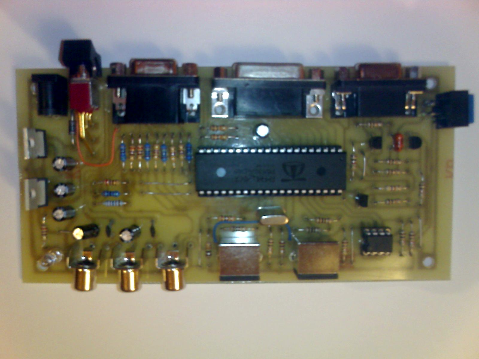
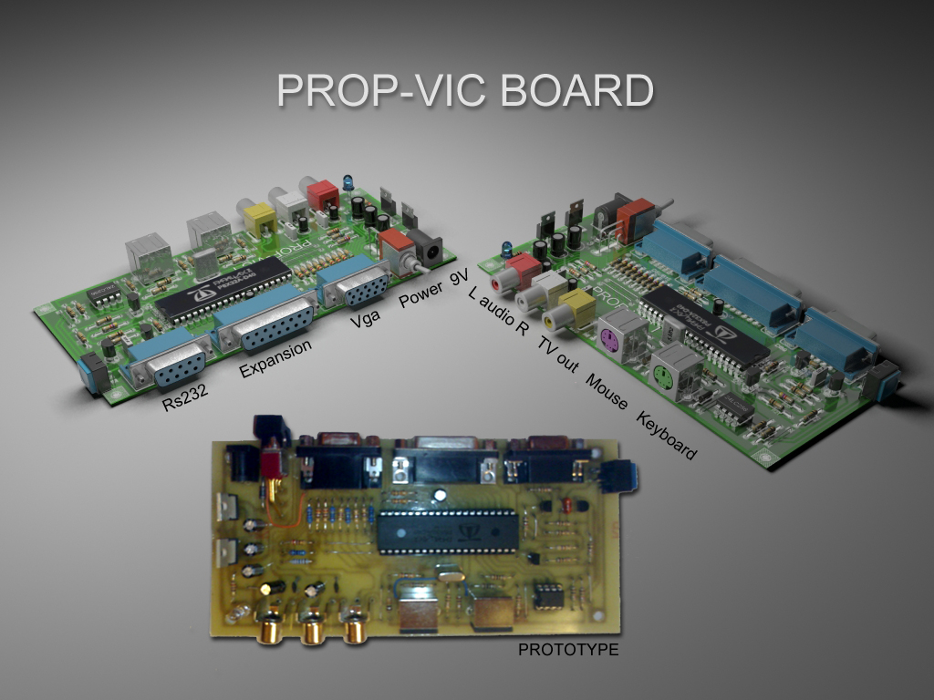
Project Complete - PROP-VIC Board (New!)
Hello everyone!
As I promised, the public all schemes relating to·project PROP-VIC Board in format WinZip file.
For any questions please contact me via email.
I state that this project is remarkably simple, because can be mounted quickly by any hobbyist.
And purposely designed single-density PCBs.
Sorry for the various jumpers (two really horrible), but the rest seems clean.
Now that I finished, I can give me to programming in Spin.
Good assembly to all!
Bye!
Lucas 68


Comments
Wow that looks like A very nice board. Always nice to see A single sided layout for home reproduction. A few wire links are never A problem!
I hope you will have endless hours of fun programming your new hardware in Spin, and other available languages.
With regards
Mike.
Wow, that's a really nice looking, feature rich board.
Do you mind me asking what software package you used to design it?
Anthony
▔▔▔▔▔▔▔▔▔▔▔▔▔▔▔▔▔▔▔▔▔▔▔▔
"powered by Propeller" domed stickers $1.50 - Find them here
Check out my Design and Technology project for my Higher School Certificate www.ecosureblog.net
With that many on board conectors single sided was bound to happen, unless you can do through hole plating. I often spend more time getting the last few jumpers tidied up than the rest of the layout. A couple of "multi-directional jumpers" aka airwires never hurts and then project finally gets made. On the last version of "Drac_Blade" I allowed myself some angled jumpers!
I see that most of it is the same as a demo board, so that will encourage its use. This was my attempt to be as flexible as possible, if a bit messy. It used to be an Arduino, sorry, sorry ....
▔▔▔▔▔▔▔▔▔▔▔▔▔▔▔▔▔▔▔▔▔▔▔▔
Style and grace : Nil point
Post Edited (Toby Seckshund) : 1/17/2010 11:53:14 AM GMT
The software I used for the design and Eagle 5.6, sorry if I missed this mentioned in previous post.
For the presentation of the board, I used 3D Studio Max 2010, creating a library of components to actual size, My avatar was created equally.
This is my method for each project, I intend to develop a board with more opportunities for expansion, always single-density, easy to install, configurable via dip swich.(For example, included (4 XTAL-Slot SD CARD-Flash Ram)
Obviously the current board and 100% compatible with that of Parallax.
I opted for the installation of all the connectors on the board, precisely because the wiring was minimized, with the disadvantage of having some bridge to be welded.
Toby, I see that the layout of your project and very neat, and is based precisely with the idea of designing PCB easily and fast, really good!
Hi!
Lucas 68
▔▔▔▔▔▔▔▔▔▔▔▔▔▔▔▔▔▔▔▔▔▔▔▔
For me, the past is not over yet.
Laying out a board like the DemoBoard isn't tricky until you want the components to be at exactly certain positions, as in all the conns on one edge etc. My attempt has all the pins presented to the top breadboard (except the P8 and P9 which do the sigma delta high speed bits) and there are loads of links to isolate the Prop from Vid, VGA, KBD and mouse resistors. I put a 8 way 10K pullup on P0-P7 for the SD cards, but it can be a pain for other things. I should fetch it out.
Still it did evict an Arduino, which should please a few, around here. The Sony case was less obvious in that mode and was the work disguise. Now they all know that coloured sections, on the PC, means Prop stuff, from a hundred yards away.
▔▔▔▔▔▔▔▔▔▔▔▔▔▔▔▔▔▔▔▔▔▔▔▔
Style and grace : Nil point
Very nice 3D models.
My question ... It is posible to have that 3D libry parts from You?
Regards
Christoffer J
▔▔▔▔▔▔▔▔▔▔▔▔▔▔▔▔▔▔▔▔▔▔▔▔
Nothing is impossible, there are only different degrees of difficulty.
For every stupid question there is at least one intelligent answer.
Don't guess - ask instead.
If you don't ask you won't know.
If your gonna construct something, make it·as simple as·possible yet as versatile as posible.
Sapieha
The design work on the Prop-Vic board and was done manually, not using the function autoruote Eagle 5.6 for connections, being single-sided PCB, as you see it is quite simple.
For the next try to make use of that function.
I make a clarification, the pin8 sigma delta-9 are available for download on the connector for expansion, I have integrated the microphone because it seemed more useful to have two pins more.
As for the 3D library, can be made available as soon as completed.
Hi!
Lucas.
It started out as a Sony BetaCam cassette case, with a home made Arduino board in it (hence the apologies, now that I have uttered that word again, sorry (again)). that board got evicted and a sort of DemoBoard went in along with all the usual connectors and a 3.3 V reg. I never had the chance to use it as I intended as the gits made me busier.
I was aware that the hairy wiring all over the place would stuff any chances of fast signal working, but I did get it to run CPM as a DracBlade with all the latches and 512Kb memory chips in the breadboard with even more long wire links! I will have to dig it out again but I have a simpler USB unit that I have to use out on the road.
Alan