

Project completed, thanks to all!
 ManAtWork
Posts: 2,368
ManAtWork
Posts: 2,368
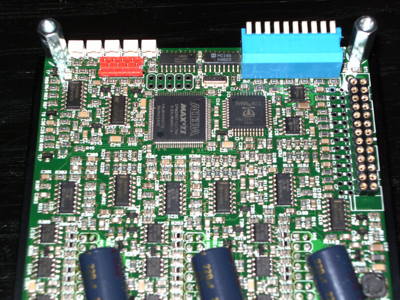
Hello,
I'd like to thank everyone for the great support in this forum. I just finished my propeller project wich will go into production tomorrow. Without you this would not have been possible or at least would have taken much more time and money.
In the attached picture you can see one of the prototype boards. It's a three axis stepper motor driver which can deliver up to 5 amperes to each motor at a supply voltage of up to 55V. One of·it's key features is a highly optimized current control technique that eliminates any staircasing in the current waveform and therefore drives the steppers without any "steps". Instead a true sine wave is seen on each winding. This makes it possible to run the motors with very low noise and vibration from zero to 4500rpm.
The propeller was the perfect choice for this project because it made it possible to integrate the controllers for all three motors into a single chip, greatly reducing board space and cost. I have to say that the parallax crew has done a really good job developping the propeller. Although sometimes a little hard to understand,·this chip is just·amazingly efficient, both in hardware and software.
I also want to especially thank Ale for his great simulator which was a great help debugging my code. As I had to use all of the IO pins of the propeller·(yes, all of them) I otherwise had no really comfortable way to test and debug.
I also thank Mike Green, BradC, Timmoore, PhiPi, Bean, Kye,·MagIO2 and all others for answering my questions. Although I have seen many microprocessors befor I had to start as a total beginner because the propeller is totally different. But it was worth the effort and it was also fun.
I wish you all a happy and successful new year
803 x 602 - 203K
Comments
Bill
▔▔▔▔▔▔▔▔▔▔▔▔▔▔▔▔▔▔▔▔▔▔▔▔
Nyamekye,
Well done! And thanks a lot for the honorable mention. Happy new year!
Can you shape the drive wave?
▔▔▔▔▔▔▔▔▔▔▔▔▔▔▔▔▔▔▔▔▔▔▔▔
Signature space for rent!
Send $1 to CannibalRobotics.com.
@MagIO2: You can buy it here: http://www.sorotec.de/shop/product_info.php/language/en/info/p1458_triple-beast.html/. And no, i don't sell propeller chips. Unfortunatelly, the handling overhead would be more than the small discount I get.
@CanibalRobotics: Do you mean if I can change the waveform? Yes, you can currently select one of two waveforms with a DIP switch. High quality motors run best with a pure sine wave. Cheaper no-name motors have a slightly distorted sine wave. They run smoothest with 3% of the 3rd overtone added. Theoretically I could use any arbitrary waveform as I calculate a modified sine table in RAM and use it instead of the ROM table.
@Sal Ammoniak: That's deceiving, you don't see all of them.
And yes, the board looks too well for a prototype, of course. The first one had lots of patch wires on it... (see below)
Thanks for the good wishes
Very neat. I'm presently working on a 3 axis using the SLA7062. I think I'd quit if my parts count got that high. That's a truely neat board with really kick-butt specs. Hope you make some dough with it.
I don't wanted to discourage anyone. Those integrated stepper drivers are perfect for low power applications like automotive actuators (backview mirrors, adjustable headlights etc.), robotics, pen plotters and so on. But they are all limited to ~45 volts·and 2 or 3 amperes. If you want higher power (for CNC applications) they get very expensive. For example the SA57, a full bridge driver for 5A 60V, costs >$12 and you need 6 of them to drive 3 motors. It's much cheaper to use discrete components.
I have my own pick&place machine, so I don't care much about the part count as long as assembly time is not the bottleneck and everything works reliable. For the same reason I don't use parts smaller than 0805. My machine·assembles a board in around 10 minutes·with no·problems. Mechanical assembly and testing takes longer, so why care about part count.
So if your target systems are smaller devices and you want to do it as simple as possible, go ahead. I see no objections using an integrated driver like the SLA7062. However, you won't win many prices in the CNC area. All higher power steppers are bipolar.
Cheers
Can I ask what software you used to make the gerbers and how many layers is it. I use Ultiboard by national instruments and I could not come close to making a board that dense.
I also go through advanced circuits who are so so when it comes to dense proto-boards.
Congrats.
Thanks for the mention of the high power IC package. There is only so far it goes in design for me before the fun stops.
▔▔▔▔▔▔▔▔▔▔▔▔▔▔▔▔▔▔▔▔▔▔▔▔
Links to other interesting threads:
· Home of the MultiBladeProps: TriBlade,·RamBlade,·SixBlade, website
· Single Board Computer:·3 Propeller ICs·and a·TriBladeProp board (ZiCog Z80 Emulator)
· Prop Tools under Development or Completed (Index)
· Emulators: CPUs Z80 etc; Micros Altair etc;· Terminals·VT100 etc; (Index) ZiCog (Z80) , MoCog (6809)
· Search the Propeller forums·(uses advanced Google search)
My cruising website is: ·www.bluemagic.biz·· MultiBladeProp is: www.bluemagic.biz/cluso.htm
That is almost as bad as a board we build for a customer. 308 components, 57 different parts, 80% 0402. We hate it, but he does keep coming back. Also....it's lead-free.
You did an outstanding job with the design and assembly of the board.
James L
▔▔▔▔▔▔▔▔▔▔▔▔▔▔▔▔▔▔▔▔▔▔▔▔
James L
Partner/Designer
Lil Brother SMT Assembly Services
Are you addicted to technology or Micro-controllers..... then checkout the forums at Savage Circuits. Learn to build your own Gizmos!
I use Eagle as layout software. "Eagle" means "easy applicable graphical layout editor" and it's exacly that, basically a painting program with electrical design rule checker. It has absolutely none of the nice features of more sophisticated (and more expensive) programs like trace impedance calculation, electrical simulation, thermal simulation and so on. The autorouter is terribly bad, I'd call it "pessimizer". But I do all routing manually.
Careful layout is important when you have high power devices near to low voltage analogue signals. High density sometimes helps because inductance and radiated noise depends on the enclosed area of a trace loop. Less area means less ringing. The board has four layers which is neccesary to fit all wide high current traces underneath the components and to allow filled ground and power planes for the low voltage section.
Hello James,
yes, I have to. You know, when you say "the project is completed", Murphy says "theres always one more bug". I forgot three pulldown resistors.
Cheers
I think it's way cool to see the propeller there in that project. Thanks for sharing that with us!
Apex aka Cirrus Logic makes H-bridges well over 100A but they are all damn expensive. It's much cheaper to make discrete bridges. Just have a look at the example schematic in the IR2104 application notes. An IRF540N costs <$1 and can handle 100V and 30A (well around half of that at high temperatures, to be safe). It only get's complicated if you need full short circuit protection.
When to use slow and fast decay is a science on it's own. I use a sophisticated commutation method that self adapts to the slope of the waveform and the demand of the load. That's what the Altera CPLD is for. If you want to start simple I'd do it like the current geckos: use slow decay when the motor stands still and fast decay otherwise. That keeps the motor cool and quiet while standing still and doesn't need complex logic.
There's another scheme that works quite well (at least for coarse resolutions up to quarter or 1/8 microstepping): Use fast decay until the current is near the nominal value, use slow decay then until the next step. But that doesn't work for high resolution, continous sine wave or when the motor is feeding back energy.
Hi Smoopy,
I payed 5000 euros ($7000) for·the (used) machine·with 100 feeders. This·was relatively high compared to similar offers at ebay. But I saw the machine running at the former owner's shop and that is something that is worth very much. When you buy "cats in bags" at ebay they often don't tell you that an important part is broken and you're left alone with a useless heap of scrap. My machine is built very simple. If something breaks I can repair most of it on my own. I·don't want to·change it against a $iemens or other well-known brand where you pay more for spare parts and maintenance per year than for my whole machine.
Cheers
just an update... This is the first CNC machine that will be·sold with my propeller powered stepper motor controller. It still looks a bit ugly without paint. But the fabrication out of laser cut and bended sheet metal is very promising. It allows for low production cost while still maintaining relatively high rigidity compared to aluminium extrusion designs.
http://www.auracher-lasertechnik.de/Forum/GP10050/Video1.avi
The first video demonstrates the smooth, low noise and low vibration·motion at low speeds. The next shows the maximum rapid speed:
http://www.youtube.com/watch?v=4sEKETnqL4o
And this one shows fast short moves in all directions to demonstrate the acceleration capabilities.
http://www.youtube.com/watch?v=ZA6jWR2r9ck
Cheers
T o n y
the Altera CPLD does all the low level stuff that is time critical: current control loops and·overcurrent protection. Additionally I use some spare pins as IO expansion (shift register). Another important thing is copy protection. Actually, except for the copy protection, a second propeller could also do the job. But this would be more expensive (Altera ~$3.50, Propeller ~$7). The current loop needs to be very fast and would require one cog per winding (two per motor).
Cheers