

Home made Development Center
 Tony B.
Posts: 356
Tony B.
Posts: 356
I decided to put this project here because it is for the BS2 and I didn't know how many look at the Completed Projects or Sandbox forums.
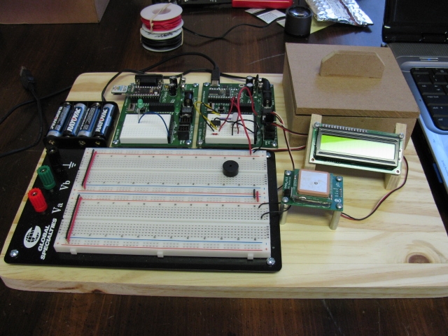
I made the Development Center for many reasons. One, I was tired of trying to keep my components together and safe. Second, Sometimes I work on projects in different places and needed an easy way to move the components around. Third, the bread board area on the BOE (Board of Education #28850) was just to small for most projects. Fourth, I was tired of chasing down bad connections with jumper wires because I accidently moved or bumped something. Well I could go on and on, but I think you get the idea and see from the pictures that this gives me a far better way to work on electronic projects.
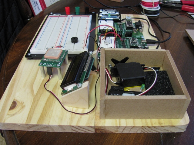
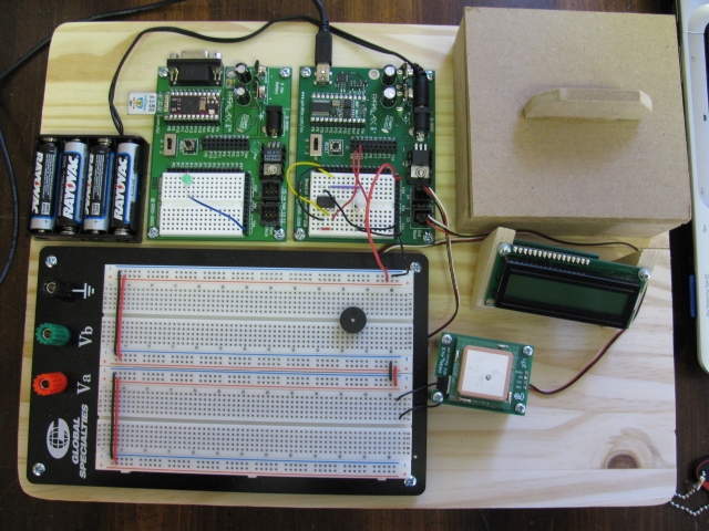
The base board measures14 1/2" x 11". This size gave me enough room for all the components you see in the attached photos and for a small work area and 4 1/2" x 4 1/2" x 1 1/2' storage box (I'd make the box 2" deep or deeper). The LCD (#27977) is mounted on angled blocks to make viewing easy for me. I first attached the blocks to the LCD and then glued the unit to the base. You may have noticed that one BOE as a BS2 and the second is running a Spin Stamp (#SS1-IC with Prop Clip #32200). This allows me to try a project idea with the BS2 (with which I have far more experience) and then port it over to the Spin Stamp learning Spin Code. I will admit my focus for the last four months has been working learning how to work with the Propeller Chip. Power can be supplied by either the Parallax AA battery pack (#700-00038) or the Parallax 7.5v 1 amp power supply (#750-00009). I run mostly on the power supply, but the AA battery pack allows for freedom to use the board anywhere like last night when my son and I played with the GPS Sensor driving around the country side. And finally the large breadboard area makes breadboarding a snap. To power the breadboard I run jumpers from whichever BOE I am using being. I connect through the power header next to the servo headers (maybe able to see in photos).
Why is there a project on the small BOE breadboard? It is from learning how to use my Parallax USB Scope. Never removed it because it makes a great circuit to show how the scope works to others.
Hope this helps you to get better organized so you can have fun with this great hobby instead of chasing down bugs in wiring or maybe to come up with your own ideas of a Development Center that fits your needs. It would be great if you could post them.
Tony
I made the Development Center for many reasons. One, I was tired of trying to keep my components together and safe. Second, Sometimes I work on projects in different places and needed an easy way to move the components around. Third, the bread board area on the BOE (Board of Education #28850) was just to small for most projects. Fourth, I was tired of chasing down bad connections with jumper wires because I accidently moved or bumped something. Well I could go on and on, but I think you get the idea and see from the pictures that this gives me a far better way to work on electronic projects.
The base board measures14 1/2" x 11". This size gave me enough room for all the components you see in the attached photos and for a small work area and 4 1/2" x 4 1/2" x 1 1/2' storage box (I'd make the box 2" deep or deeper). The LCD (#27977) is mounted on angled blocks to make viewing easy for me. I first attached the blocks to the LCD and then glued the unit to the base. You may have noticed that one BOE as a BS2 and the second is running a Spin Stamp (#SS1-IC with Prop Clip #32200). This allows me to try a project idea with the BS2 (with which I have far more experience) and then port it over to the Spin Stamp learning Spin Code. I will admit my focus for the last four months has been working learning how to work with the Propeller Chip. Power can be supplied by either the Parallax AA battery pack (#700-00038) or the Parallax 7.5v 1 amp power supply (#750-00009). I run mostly on the power supply, but the AA battery pack allows for freedom to use the board anywhere like last night when my son and I played with the GPS Sensor driving around the country side. And finally the large breadboard area makes breadboarding a snap. To power the breadboard I run jumpers from whichever BOE I am using being. I connect through the power header next to the servo headers (maybe able to see in photos).
Why is there a project on the small BOE breadboard? It is from learning how to use my Parallax USB Scope. Never removed it because it makes a great circuit to show how the scope works to others.
Hope this helps you to get better organized so you can have fun with this great hobby instead of chasing down bugs in wiring or maybe to come up with your own ideas of a Development Center that fits your needs. It would be great if you could post them.
Tony
Comments
Here is my not so portable work-center
▔▔▔▔▔▔▔▔▔▔▔▔▔▔▔▔▔▔▔▔▔▔▔▔
Mike2545
Post Edited (Mike2545) : 1/6/2010 12:22:13 AM GMT
Prettybird - Thanks for the suggestion. I have plenty of nicad packs from my RC Cars lying around.
Mike2545 - Nice work area. Looks like you got just about everything you need. Is the device in the center back a programmer and does it allow you to run the PIC and BS2 from it? I started with PICs using PIC Basic and EPIC programmer form Micro Engineering Labs. I then discovered the BS2 and the BOE-BOT have been using Parallax products since then. I think I'll pull my PIC stuff out and see if I can get them to communicate with my BS2 and Spin Stamp. Just might come in handy one day.
I generally use the Basic Stamp for Development of a project or parts of code I am learning, then I can easily switch over to Pic Basic Pro to allow me to put the code in a PIC. The red buttons switch the Pickit programmer to the desired Pic to be programmed via relays, I have also put in the DIN connector for ICSP.
Past projects have run Stamps out of memory or variables, as a former PIC man yourself, you know there are several "flavors" of Pics to choose from, I settled on the 18F1320; 8K of program space and a slew of variables to be had. The Pic Basic Pro uses the same syntax (mostly) as the Basic Stamp.
Cross communication is not a problem between the Stamp and PIC's in my experience.
Here are a few pictures of the inside during assembly:
Enjoy...
▔▔▔▔▔▔▔▔▔▔▔▔▔▔▔▔▔▔▔▔▔▔▔▔
Mike2545
Post Edited (Mike2545) : 1/6/2010 11:24:30 PM GMT
Nice Work! Thanks for sharing the info and photos. I really enjoy looking at others projects.
So many projects, so little time.
Thanks,
Tony