Shop OBEX P1 Docs P2 Docs Learn Events
IR on Stingray — Parallax Forums

IR on Stingray

BocephusBocephus Posts: 58
edited 2011-08-11 06:46 in Robotics
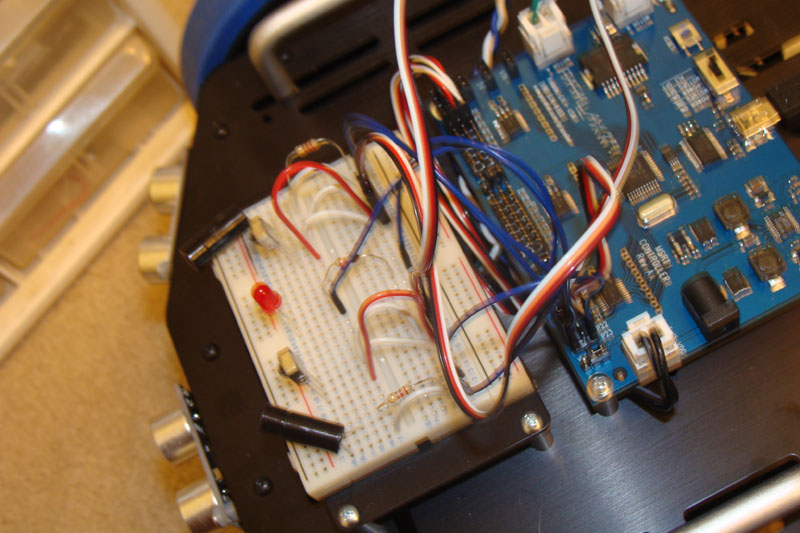
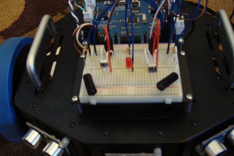
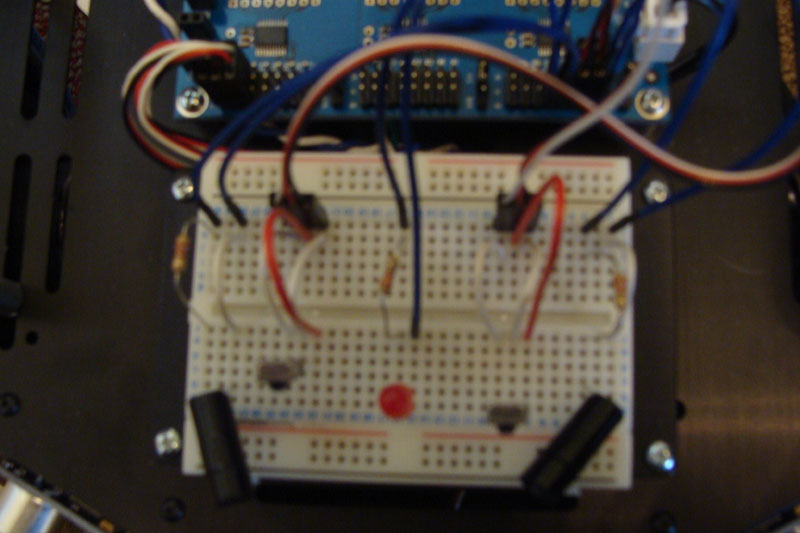
I am attempting to add IR detection for my Stingray but the IR never detects anything. I'm not sure if my mistake is in the code or the circuit. I'm using the IR Detector object. Any assistance or guidance is appreciated.

dira[noparse][[/noparse]IR_R_LED..IR_L_LED]~~ 'output
  dira[noparse][[/noparse]IR_Motion_LED]~~
  dira[noparse][[/noparse]IR_L_Rec]~
  dira[noparse][[/noparse]IR_R_Rec]~
  outa[noparse][[/noparse]IR_R_LED..IR_L_LED]~~
  outa[noparse][[/noparse]IR_Motion_LED]~  
  
  IR_L.init(23,22)
  IR_R.init(20,21)
  
  repeat
    if IR_L.object
      'if IR_L.distance < 10
      Counter := cnt
      !outa[noparse][[/noparse]IR_Motion_LED]
      waitcnt(Counter += 10_000_000) 
      !outa[noparse][[/noparse]IR_Motion_LED]
    if IR_R.object
      'if IR_R.distance < 10
      Counter := cnt  
      !outa[noparse][[/noparse]IR_Motion_LED]
      waitcnt(Counter += 10_000_000) 
      !outa[noparse][[/noparse]IR_Motion_LED]
800 x 533 - 128K
800 x 533 - 98K
800 x 533 - 90K
«1

Comments

  • BocephusBocephus Posts: 58
    edited 2010-01-01 21:35
    Hello, I am still trying to get this to work. Below is an update of where I am. Can anyone help me figure out why I get no signal? I'm sure I must be doing something wrong.

    CON
    
      _clkmode = xtal1 + pll16x
      _clkfreq = 80_000_000
    
      IR_Motion_LED = 19 ' motion detected indicator LED
      IR_R_LED      = 20 ' infrared LED, changed to 1k resistor
      IR_R_Rec      = 21 ' receiver added 220 resistor
     
    OBJ
              
      IR_R  : "Ir Detector"
    
    PUB main
    
      dira[noparse][[/noparse]IR_R_LED]~~   
      dira[noparse][[/noparse]IR_Motion_LED]~~
    
      IR_R.init(IR_R_LED,IR_R_Rec)
      
      repeat
        if IR_R.object
          !outa[noparse][[/noparse]IR_Motion_LED]
          waitcnt(40_000_000 + cnt)
          !outa[noparse][[/noparse]IR_Motion_LED]
    
     _____
     |   | <- IR Receiver
     | 0 |
     |___|
     | | |
     | | |
     | | |______ +
     | |________ -
     |            220
     |__________/\/\/\___o P21 
    
    
      _
     (_)   <- IR LED
     | |
     | |
     | |________ -
     |            1K
     |__________/\/\/\___o P20 


  • SRLMSRLM Posts: 5,045
    edited 2010-01-01 22:23
    You may want to take a look at this thread: http://forums.parallax.com/showthread.php?p=856735

    You may be experiencing a similar problem. To see if you are, you'll want to get a multimeter out and see if the signals are present or not on the receiver. If they are, then try writing a small program that simply continuously pulses out on the IR LED, and displays (via terminal or visible light LED or something) what the input is seeing (0 or 1). If the results are different than the multimeter says, you're in the same trap. From there I'd experiment with different sized resistors (probably a higher value).

    There is some discussion in the Propeller Education book (pdf on Parallax site) about the IR detectors that might help. I believe that it has some simple code that you can hack if needed.

    ▔▔▔▔▔▔▔▔▔▔▔▔▔▔▔▔▔▔▔▔▔▔▔▔
    Powered by enthusiasm
  • Mike GreenMike Green Posts: 23,101
    edited 2010-01-01 22:26
    1) Make sure you've got the IR detector wired correctly. The pins as you've shown them are as seen from the front (sensor) side of the device.

    2) You didn't say what IR Detector object you're using. There are several in the Object Exchange. Please identify it more clearly.
  • BocephusBocephus Posts: 58
    edited 2010-01-01 22:53
    Thanks SRLM and Mike Green.

    SRLM, I'll check the thread you suggested to determine if that is my problem.

    Mike Green, I drew the connections as I have them so I think I am good there. I got the files from my Propeller folder on my computer and I am unsure where I got them from, or when I downloaded them for that matter, so I am attaching the 2 object files used.
  • Mike GreenMike Green Posts: 23,101
    edited 2010-01-01 23:14
    With a 1K resistor in series with the LED, you're only getting about 1.5mA through the LED which isn't a lot of current and the LED will be fairly dim. Try something more like the 220 Ohm resistor or even 100 Ohms. The IR detector is ok with a 220 Ohm resistor. Make sure the IR detector's power source is 5V.

    You can often use a VCR to check if an IR LED is working ok. The IR will show up on the screen if it's pointed at a working IR LED.
  • BocephusBocephus Posts: 58
    edited 2010-01-02 22:09
    I found another object to use for the square wave and the Full Duplex Serial Plus for debugging. I swapped the IR LED with a regular one and the light comes on. I also swapped the 1k out and put the 220 back. The receiver shows 4.9v on the multimeter. I tried using the remotes I had around to see if the receiver would change states. I moved the robot around hoping to change states as well but the state remains at 0 no matter what I do. I'm not sure how to proceed debugging my issue.

    CON
    
      _clkmode = xtal1 + pll16x
      _clkfreq = 80_000_000
    
      IR_Motion_LED = 19          
      IR_R_LED      = 20
      IR_R_Rec      = 21
    
      HOME = 1, CR = 13, CLS = 16, CRSRX = 14, CLREOL = 11
    
    OBJ
              
      SqrWave       : "SquareWave" 
      Debug         : "FullDuplexSerialPlus" 
    
    PUB main | IR_State 
    
      dira[noparse][[/noparse]IR_Motion_LED]~~                      ' IR Begin
      
      'Start 38 kHz square wave
      SqrWave.Freq(0, IR_R_LED, 38000)           ' 38 kHz signal &#8594; Pin
      dira[noparse][[/noparse]IR_R_LED]~                            ' Set I/O pin to input when no signal needed
    
      'Start FullDuplexSerialPlus
      Debug.start(31, 30, 0, 57600)              ' Start FullDuplexSerialPlus
      waitcnt(clkfreq * 2 + cnt)                 ' Give user time to click Enable.
      Debug.tx(CLS) 
      
      repeat
        ' Detect object.
        dira[noparse][[/noparse]IR_R_LED]~~                         ' I/O pin &#8594; output to transmit 38 kHz
        waitcnt(clkfreq/1000 + cnt)              ' Wait 1 ms
        IR_State := ina[noparse][[/noparse]IR_R_Rec]                ' Store I/R detector output
        dira[noparse][[/noparse]IR_R_LED]~                          ' I/O pin &#8594; input to stop signal
        waitcnt(clkfreq/10 + cnt)
    
        Debug.str(String(HOME, "State = "))      ' State always shows 0
        Debug.Dec(IR_State)
        Debug.tx(CLREOL)
        
        if IR_State
          !outa[noparse][[/noparse]IR_Motion_LED]
          waitcnt(10_000_000 + cnt) 
          !outa[noparse][[/noparse]IR_Motion_LED]                   ' IR End
    
  • John AbshierJohn Abshier Posts: 1,116
    edited 2010-01-03 01:07
    Most of the times frequency for the Prop is defined as

    CON

    _CLKMODE = XTAL1 + PLL16X
    _XINFREQ = 5_000_000

    Page 38 of Prop Manuas v1.1 says that _clkfreq is read only

    John Abshier
  • BocephusBocephus Posts: 58
    edited 2010-01-03 07:35
    John Abshier, one can define either _CLKFREQ or _XINFREQ in the CON section. The other will be calculated based on the application defined one and the _CLKMODE.
  • BocephusBocephus Posts: 58
    edited 2010-01-05 08:07
    Me again, I really want to make this work. In the "Propeller Education Kit Labs - Fundamentals v1.1" pdf file on page 148 it shows an IR setup. So I located my demo board and reproduced the circuit I have been debugging on the stingray to see if I could get it working on the demo board. I replaced the resistors with 1k each on the LED and the receiver like it shows in the pdf. It works! I quickly realized I needed to change the code from "if IR_State" to "ifnot IR_State." It works as expected on the demo board so I experimented with some different resistor values on the stingray, but I've still had no success. Does this mean I will have to disable the level shifters as mentioned in the link SRLM provided?
  • Roy ElthamRoy Eltham Posts: 2,998
    edited 2010-01-05 09:55
    I'm just learning this stuff myself, but whatever circuit you had working on the demo board was based around connecting to the Prop pins directly which are 3.3 volts and on the Stingray robot board you are connecting to them through level shifters that change it to 5 volts.
    You have to adjust the circuit for the difference on voltage, which I believe means using larger resisters to the LEDs and smaller resisters to the recievers. One of you electronics experts correct me if I am wrong...

    I think you might try using a 1.8k resistance (maybe 2.2k resister is the closest?) to the LED (this is based on the spec sheet on the parallax store for the IR LED that says it has a max 1.5 forward voltage which is lower than a typical color LED), and no resister on the reciever since it outputs between 0 and 5 volts (according to the data sheet linked to on the parallax store).

    ▔▔▔▔▔▔▔▔▔▔▔▔▔▔▔▔▔▔▔▔▔▔▔▔
    Check out the Propeller Wiki·and contribute if you can.

    Post Edited (Roy Eltham) : 1/5/2010 10:02:20 AM GMT
  • CannibalRoboticsCannibalRobotics Posts: 535
    edited 2010-01-05 13:00
    So glad to know it's not me. I've been scratching my head over this too. I bought the StingRay as a home tinker toy. I got frustrater with the IR sensor thinking, well, now I have to take it to the shop to see why this does not work. So, last night I decided I'm going to try to back door the 3.3-5v converter and take the sensor output directly to the prop pin on the header. I'm determined to solve this at home.
    I'll let you know how it goes.
    Jim-

    ▔▔▔▔▔▔▔▔▔▔▔▔▔▔▔▔▔▔▔▔▔▔▔▔
    Signature space for rent!
    Send $1 to CannibalRobotics.com.
  • CannibalRoboticsCannibalRobotics Posts: 535
    edited 2010-01-05 22:21
    OK,
    so I got it up on the scope. The little silver, metal case IR receivers seem to have a couple of issues.
    The signal is inverted and it can not seem to overcome the 3.3-5v converter. If I power it up and run the output directly into the scope, I get clean 5->0v square pulses. If I hook it up to the converter through 100 up to 10K resistor, it goes flat or way too low.
    The only way I have been able to get them to work is by placing a 1K pull UP resistor on the output of the sensor and connecting the output directly to the prop converter pin.
    It seems to work with Bob Belleville's IR code.
    J-

    ▔▔▔▔▔▔▔▔▔▔▔▔▔▔▔▔▔▔▔▔▔▔▔▔
    Signature space for rent!
    Send $1 to CannibalRobotics.com.
  • BocephusBocephus Posts: 58
    edited 2010-01-06 03:16
    Thank you Jim. So I will have to install the bypass and translator headers in order to have IR. Does this mean any sensor with an inverted signal will require this technique?

    Thanks to everyone for the troubleshooting assistance.
  • SRLMSRLM Posts: 5,045
    edited 2010-01-06 06:25
    Bocephus said...
    Thank you Jim. So I will have to install the bypass and translator headers in order to have IR. Does this mean any sensor with an inverted signal will require this technique?

    I don't think the problem was the inverted signal. Rather, the level changing chip that was used has some requirements that the 5v side has to accommodate, and the circuit wasn't doing it.

    As a side note, I think Parallax should come out with a number of reference circuits for the Stingray. There needn't be many, but things like buttons, IR detectors, LEDs, QTIs, etc. would be a good start.

    ▔▔▔▔▔▔▔▔▔▔▔▔▔▔▔▔▔▔▔▔▔▔▔▔
    Powered by enthusiasm
  • rpdbrpdb Posts: 101
    edited 2010-02-11 01:25
    Just a not-so-quick note on LEDs. You need to·know what the forward voltage is and the max forward current rating of the diode you are using.· Standard LEDs forward voltage Vf vary with color and rated brightness, and will often have a forward voltage·in the range·1.7 -·3.0 volts with a current of 20 - 30 mA, infraRed often·much higher ie 50 mA.

    So a quick example: Std. red LED Vf 1.7v If 30mA max (so I'll run it at 20 mA to avoid absolute max rating).

    ·Take your supply voltage ie 5.0V and subtract the forward voltage across the diode junction ie 1.7Vf.

    This leaves 3.3V that will be across your series current limiting resistor. Use Ohms Law 3.3V/20mA = 165 ohms. Resistors of the carbon film type come in standard "series of values" ie 1.0, 1.2, 1.5, 1.9, 2.0, 2.2 etc. +/- 5%. Select something close for example a 150 ohm resistor should work fine (3.3V / 150ohms = 22mA)

    If you use a 1k ohm you will get 3.3v / 1000 ohms = 3.3mA hardly enough to light the LED!

    Infrared LEDs (940nm wave length) that are used for transmit recieve pairs are·sometime rated at up to 50·mA so you might need something closer to 100ohms or less, and·because you are pulsing the LED ie 50% duty cycle means you could run Iforward at 100 mA and be safe. Keep in mind to check·if this runs close to the max rating of the MRS1 translator chip output rated current.

    If you have a scope take a look at the output of the reciever. That output probably "floats" when the reciever is off. You have to determine if it floats high or low to see if it gets to the translator chips rated "Voltage input high/low levels" to see if you need either a pull up or pull down resistor.

    You can also some times use a cellPhone camera·to see if you have IR from your emitter.

    ·
  • Headache07Headache07 Posts: 3
    edited 2010-06-14 02:07
    Can anyone here show mi the circuit diagram for the stingray IR detector.. so i could fix it n try out see whether it wrks.. thx
  • polbitpolbit Posts: 25
    edited 2010-11-25 09:53
    Sorry to resurrect an old thread, but has anybody been able to connect an IR circuit without disabling the translators? I really don't want to have to soldier headers to it, and disable the 3-pin cable connectors. I've decided to play with the Stingray again this long weekend, but right away I'm back to the same problem - what works great on the Proto board doesn't on the Stingray board...

    Polbit
  • ratronicratronic Posts: 1,451
    edited 2010-11-25 13:15
    polbit, I have used the parallax ir detector without bypassing the translators. See this thread - http://forums.parallax.com/showthread.php?t=123850
  • polbitpolbit Posts: 25
    edited 2010-11-25 20:18
    ratronic, thank you so much, don't know how I missed your post! I'll be playing with the setup as soon as family leaves :)

    Polbit
  • Ray0665Ray0665 Posts: 231
    edited 2010-11-29 07:06
    I too had problems with the level shifters on the stingray and a variety of circuits.

    So I ended up building a simple circuit using the 74HC595 serial to parallel shift register and wrote an object to control the lights without disabling the level shifters.

    A good side effect is the I have 8 outputs (and can cascade several more in groups of 8) at a cost of only 3 I/O pins.

    Attached is my object which includes the schematic, there is at least one other object in the obex to control these shift registers but I don't remember its name at the moment.

    I also built a similar circuit for the input side using the 74HC165 parallel to serial shift register but have not as yet written the object to control it, but I will, and I'll post the combined object to the exchange when I do.

    OK I just checked the obex and found two objects here are the links
    http://obex.parallax.com/objects/437/
    http://obex.parallax.com/objects/523/
  • ratronicratronic Posts: 1,451
    edited 2010-11-29 08:32
    On page 6 of the Propeller Robot Control Board manuel they have a note on what it takes to pull the inputs to either rail. My problem finding this was it is not explained in the Stingray Robot manuel which is the only manuel listed with the Stingray robot on the parallax web page for it.
  • polbitpolbit Posts: 25
    edited 2010-11-29 19:10
    Well, unfortunately it is not working for me... I tried the IR receiver with my BS2 board, it worked fine. I used it with the Stingray, nothing, using the code as downloaded, and a 4.7k resistor between pin 1 and 3 on the receiver... What am I doing wrong?
  • polbitpolbit Posts: 25
    edited 2010-11-29 19:58
    I also grabbed the Propeller Demo Board, hooked it up without any resistors, and used the irtest and parallax serial terminal to get some values. It worked great with the demo board. Same setup, but with the 4.7k resistor, on the stingray, keeps showing 255 for key value...

    Btw, my Stingray board works fine, I have 3 pings and roaming works fine.

    Any help would be greatly appreciated!

    Polbit
  • WhitWhit Posts: 4,191
    edited 2010-11-29 20:10
    polbit,

    Have you talked to tech support or Chris Savage about this? I'll bet they can help clear this up.

    I agree that the notes on the Robot Control Board data sheet and the Stingray documentation should be co-ordinated.
  • ratronicratronic Posts: 1,451
    edited 2010-11-29 21:41
    polbit - I just loaded the program into my stingray and it works for me. The only change I made to the program is the detector input pin # from 16 to 1 as that is where my current ir detector is hooked.
    The translators need to see +/- 2 m.a. to trigger them (see pages 10/11 of attached data sheet). The Parallax irdetector which is equivalent to a Panasonic PNA4601 only has a built in pull up resistor of 20K ohms that's why I choose a 4.7k, although that is right on the edge of the requirements for the translators.
    The program irtest.spin only decodes compatible Sony T.V. remotes.
    I didn't come by this setup from Parallax, so if you can't get yours to work you might give tech support a call and see what they recommend.
  • Chris SavageChris Savage Parallax Engineering Posts: 14,406
    edited 2010-11-30 08:26
    Hello everyone. The translators were original chosen to allow easy integration of 5V sensors onto the Robot Control Board, however we have obviously received much feedback indicating that there are some unforseen issues with the translators that have affected some customers. My best advice until we're able to provide a better solution would be to disable a bank of translators and use the pins directly, perhaps biasing a transistor to drive LEDs, or even in some cases for isolation.

    If it seems like we're slow to respond to the issues related to this part it is only because we're currently working on possible solutions and want to update documentation once the issues are solved rather than making several updates with test information (things we're looking into). Please bear with us and we should have something early in January or know our timeline at that point.
  • ratronicratronic Posts: 1,451
    edited 2010-11-30 09:36
    polbit - I keep P16-P23 bypassed for when I run into these issues. See the attached picture on how to bypass the translators.

    Edit: modemman just posted he was able to get it working by using a 3.3k without bypassing the translators.
    1414 x 893 - 1M
  • polbitpolbit Posts: 25
    edited 2010-11-30 17:03
    Chris, thank you for the response, I have no doubt that Parallax is on top of this, one of many positives when buying Parallax products :)

    ratronic, I've decided to do exactly that for now, since I'll need it for more sensors. But will definitely try 3.3k resistor for the IR...

    Polbit
  • polbitpolbit Posts: 25
    edited 2010-12-02 06:41
    ok, 3.3K resistor did it! Now onto line following and trying to use the sensors from Boe Bot kit :) Hopefully when I'm done I'll have a Stingray that will follow lines, use a remote to overide that, and use 4 pings to override all when it's too close to an object or the line is not there... Will probably need 4 more pings to make it bulletproof, but 3 upfront and 1 back is a good start.

    Polbit
  • ratronicratronic Posts: 1,451
    edited 2010-12-02 08:04
    Polbit I'm glad the 3.3k worked. I may change the other thread to use a 3.3k only as thats what I changed mine to and it works. Start a new thread and show us your new creation when you get it running!

    other thread: http://forums.parallax.com/showthread.php?t=123850
Sign In or Register to comment.