HO Model Railroad Under SX Control (completed project with photos)
&imgdimwI've been working on this on and off for about nine months (for one of my kids who is train-crazy). Model railroads are not exactly my style, but it's been pretty fun.
I'd post this to completed projects but it's not wholly done, plus I wired it up on the fly for the most part, so pulling a schematic together will take some real work. But it's a neat setup and I thought some folks might want to see some simple solutions for a modest layout.
A few general notes -- the goal here was *inexpensive*. All the electronics were put together for about $50. All the lumber and track and roadboad came to about $100. The ATX power supply was a salvage. Cardboard armature is from old shipping boxes. A coupla Hitec servos for about $8 each. The biggest cost was easily the two model trains we bought (as gifts) for the little ones.
23A of 12v power and 17A of 5v power are provided by a fan-cooled ATX salvaged from an old Compaq desktop.
In any case, the whole thing is under micro control. A series of relays driven by a ULN2803A control power to four sections of track (two sidings and two main blocks). An Infineon 5A full H-bridge handles PWM and direction to the tracks themselves. Turnouts are handled with servos -- more on this below. Two banks of shift registers, each with it's own 2803A, provide 40 channels of 500ma per channel (sink) -- in our running demo we've got a bunch of superbright LEDs, a turn signal from an old dodge van, and some animatronic motors hooked up for "proof of concept" in running lots of blinky lightbulbs, motors, leds, etc. so we can add electric fun to the layout as time goes on (street lights that come on at night, interior lights for the tunnels, a tramway, etc.). The output registers and drivers are actually in a bank of one (5v/gnd) and four (12v/gnd), so technically there are 8 channels of 5v power and 32 channels of 12v. Outputs of the banks are accessible via .1" headers and screw terminal boards to make wiring and changes relatively easy.
There are two more output registers and drivers along with two parallel-in-serial-out input registers ('595s and '165s) -- these are used for 16 IR emitter/detector channels for loco and other detection possibilities on the layout. Currently we're only using one emitter/detector pair on one side of the siding, so when the SX is running two trains, it knows when the train is on the siding and can change the turnouts and put the other loco onto the mainline.
On the SX side, a small EEPROM is installed on the protoboard -- the application saves it's current running state to EEPROM so the layout can be powered down at any time and the app "remembers" the current positions of the turnouts, which train is "active", if one train or two are being run, etc.
We will be building a fancy control panel with knobs and dials and a speedometer and such in the future; for now 4 buttons and 2 led indicators on a perfboard handle control. But the real fun is that after two minutes of user inactivity, the layout runs itself -- randomly starting and stopping the active train; pulling the train into the siding, changing the turnouts, sending the other loco out, blinking lights, turning the airplane motor on and off etc.
Attached is a .zip with the SX app and my libraries. It's a fairly straightforward state machine setup, with some ISR based code for motor PWM, servo pulse refreshes, IR modulation for the IR emitter/detector pairs, etc. Note that the train values are "loaded" from data upon a switch -- these tables contain maximum/minimum forward/reverse limits for each loco, if the loco travels CW or CCW on the layout, "cruise" speeds, etc. Eventually I will probably move these tables into EEPROM along with other data and "hard" values to save code space, but then it would be a completed project, I guess
Photos with more detailed explanations below.

Above shows main project board on the bench before install. At bottom is a molex connector and terminal blocks for 5v and 12v power from the ATX. One 12v line is for motors, the other 12v line for accessories. One 5v line is for logic power, the other 5v line is for the 5v 500ma output drivers and for servo power.
Above the black terminal blocks is the motor driver board, which has the Infineon h-bridge, 4 SPDT relays and an on-board ULN2803A driver. The idea is that up to 8 relays could be installed for block control w/o any changes to wiring on the motor board or the main micro board. Euro screw terminals at right allow for easy connection to the layout itself.
Above the relay board is an SX-48 protoboard -- this has the EEPROM (smt) installed, along with headers for 8 servos (turnouts), UI, and SPI connections to the main output drivers (leds, accessories) and the motor driver board.
Above the SX board is the main driver board -- 5 HC595 shift registers each with UL2803A drivers associated. Two-pin SIP sockets connect the outputs of the drivers to the headers -- this lets me insert straight wire for direct connects or current limiting resistors for things like LEDs. Again, one of the registers is 5v based and four are 12v based. At the top left of the output board are two '595 registers for up to 16 IR emitters and two '165 registers for inputs from up to 16 IR detectors. IR modulation is handled by strobing the enable pins of the '595s.
There are a few funky tricks on this board that I tried for experimentation's sake. First, all the enable lines are brought out to jumper blocks next to the SPI header to the SX. Right now they are all tied low (/EN) so they are just on, but I could PWM on these lines for EACH unique output register if I wanted. Second, in an effort to make it "infinitely" expandable, the CS lines for each register are NOT tied to the micro -- rather they are tied to an eighth "master" '595 that handles which bank of '595s will be pulsed to latch output data. This master is actually the first '595 in the serial cascade, so the host shifts data out to which ever bank it will want to change, with the final shifted byte being the desired "state" of the CS lines. This byte is held for 10us or so, then cleared. The effect is to pulse the correct CS line(s). The same goes for when shifting in from the '165s -- it's a just a question of which CS line(s) were pulsed by the master '595. The master can be seen at the bottom of the board next to the power filtering caps and such.
Lastly, the serial out from the '165s and the serial in to the '595s are tied together with a 1k resistor (again with SIP socket so it can be removed) to save a pin on the host. Essentially the whole board is controlled by 3 lines (master CS, CLK, SDAT), with one extra line for IR modulation.
One last note -- I thought about having the output board be a few "slave" SXes running the darlington arrays, but in the end using the output registers was much cheaper (I paid about $5 for all the in/out registers and sockets) and it meant I didn't have to write more code for slave communication, output manipulation, etc (i.e., I could have one master program to play with). But using some slave micros would have made for much simpler physical wiring for sure.
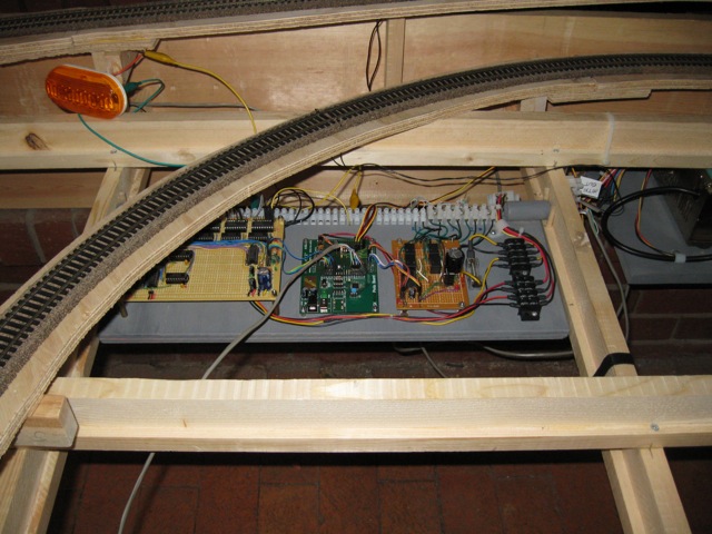
Project board in position at center rear of layout.
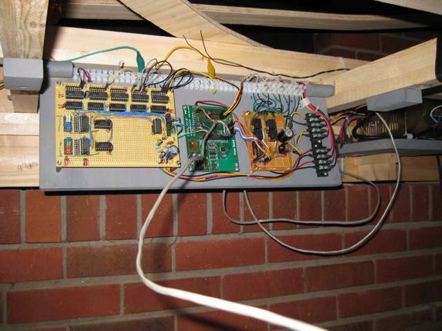
Flipping the two pivot blocks to the side lets the board "drop down" for terminal wiring changes, header access, and programming via SX-Key without having to remove anything. The long cat-5 wire is the connection to our temporary perfboard button HI.
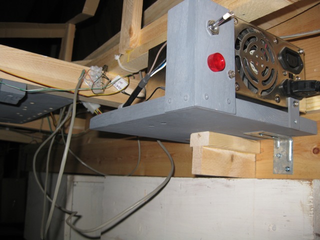
ATX power supply accessible at right of layout, with big bright red power lamp.
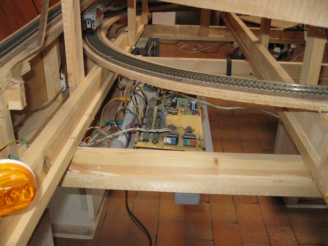
Other side of project board in situ. The colored jumper blocks are the 4pin header connectors for IR emitter/detector pairs -- 5v, gnd, detector, IR led anode. The jumper blocks let the input to the '165s be tied high so they are not floating if not in use. The cat5 cable goes to the one IR emitter/detector pair we have set up.
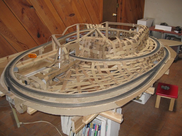
Decent overall view of the layout from last week, showing most of the scenery armature in place. At mid upper left is the 12v Dodge turn signal -- it blinks and PWM dims depending on the speed of the train when in motion. At top right is a small scale biplane mounted with music wire to a 5v, 2RPM gear motor I salvaged from somewhere. When the train(s) stop, the airplane circles around slowly above the mountain.
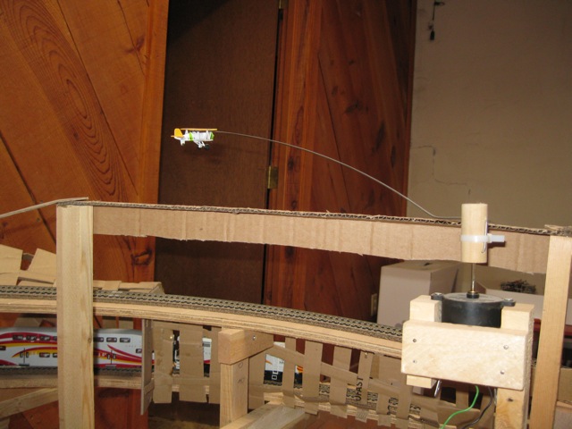
Airplane again.
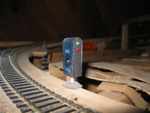
IR led emitter and turnout indicate LEDs cleverly (!) disguised as some kind of trackside structure.
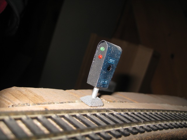
Across the tracks, a similar unit but with an IR detector inside. When the train "breaks" the beam, the input to the '165s goes HIGH.
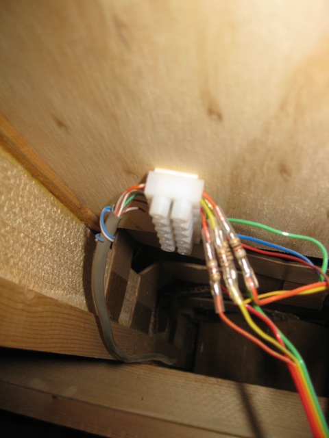
The wiring BELOW the layout for the above IR and LED setup. I pretty much put small terminal blocks wherever accessories need to be hooked up -- it has saved RADICAL amounts of time and frustration.
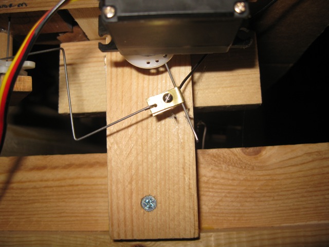
The basic setup for servo controlled turnouts. I WILL NEVER USE SWITCH MACHINES OR SOLENOIDS AGAIN. Why I didn't use servos to begin with, I'll never know. The servos are half the price of any "real" HO switch controller, they are quiet, they move *slowly* which looks really cool, and the music wire through the turnout throwbar will hold the turnout rails very tightly. And of course, servos lend themselves to attaching other nifty mechanical signals. The picture shows the music wire I threaded through the servo horn. The top of the wire (unseen) goes through the bottom of the track bed (through a slot) and into the turnout throwbar to move it. The bottom portion of the wire is tied to track power -- you can see where it makes contact with two pieces of wire inserted through the track bed support -- this is essentially a servo-controlled SPDT power "switch" that controls polarity to the turnout frog (so that the frog has the correct polarity for the loco depending on the turnout's position). Very simple, and took like 5 minutes to put together. The Z-wire bend to the left goes to a pivot/wire setup that turns an arrow sign up above to point to the siding that is in use. When the servo changes the turnout, the sign rotates slowly to it's new position. Very effective.
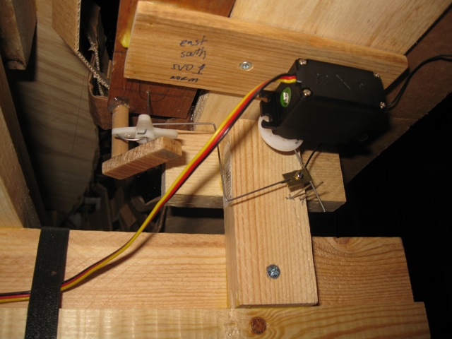
Different view of turnout setup.
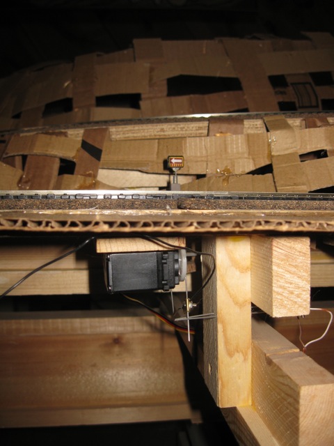
This photos shows the above and below view -- the arrow sign up top points towards one siding or the other when the servo changes the turnout.


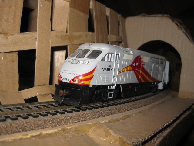
The above photos show the current scenery wrapped and painted, along with some ambient lighting we installed. The station lights only come on when the trains pull through the sidings or are parked at the station. We also hacked out some sound effects robbed from an old pushbutton train toy. The sounds are triggered by the SX at appropriate times (when leaving the station, etc).
Here's a few videos
Nighttime (more ambient but low quality): www.youtube.com/watch?v=kL-JhGtfWYY
Daytime: www.youtube.com/watch?v=Ybdf3MxS8eY
Gotta have trains!
▔▔▔▔▔▔▔▔▔▔▔▔▔▔▔▔▔▔▔▔▔▔▔▔
When the going gets weird, the weird turn pro. -- HST
create bitmap data tool: 1uffakind.com/robots/povBitMapBuilder.php
resistor ladder tool: 1uffakind.com/robots/resistorLadder.php
convert images to ascii art: 1uffakind.com/apptoys/convtoascii/
Post Edited (Zoot) : 6/30/2010 11:41:31 PM GMT
I'd post this to completed projects but it's not wholly done, plus I wired it up on the fly for the most part, so pulling a schematic together will take some real work. But it's a neat setup and I thought some folks might want to see some simple solutions for a modest layout.
A few general notes -- the goal here was *inexpensive*. All the electronics were put together for about $50. All the lumber and track and roadboad came to about $100. The ATX power supply was a salvage. Cardboard armature is from old shipping boxes. A coupla Hitec servos for about $8 each. The biggest cost was easily the two model trains we bought (as gifts) for the little ones.
23A of 12v power and 17A of 5v power are provided by a fan-cooled ATX salvaged from an old Compaq desktop.
In any case, the whole thing is under micro control. A series of relays driven by a ULN2803A control power to four sections of track (two sidings and two main blocks). An Infineon 5A full H-bridge handles PWM and direction to the tracks themselves. Turnouts are handled with servos -- more on this below. Two banks of shift registers, each with it's own 2803A, provide 40 channels of 500ma per channel (sink) -- in our running demo we've got a bunch of superbright LEDs, a turn signal from an old dodge van, and some animatronic motors hooked up for "proof of concept" in running lots of blinky lightbulbs, motors, leds, etc. so we can add electric fun to the layout as time goes on (street lights that come on at night, interior lights for the tunnels, a tramway, etc.). The output registers and drivers are actually in a bank of one (5v/gnd) and four (12v/gnd), so technically there are 8 channels of 5v power and 32 channels of 12v. Outputs of the banks are accessible via .1" headers and screw terminal boards to make wiring and changes relatively easy.
There are two more output registers and drivers along with two parallel-in-serial-out input registers ('595s and '165s) -- these are used for 16 IR emitter/detector channels for loco and other detection possibilities on the layout. Currently we're only using one emitter/detector pair on one side of the siding, so when the SX is running two trains, it knows when the train is on the siding and can change the turnouts and put the other loco onto the mainline.
On the SX side, a small EEPROM is installed on the protoboard -- the application saves it's current running state to EEPROM so the layout can be powered down at any time and the app "remembers" the current positions of the turnouts, which train is "active", if one train or two are being run, etc.
We will be building a fancy control panel with knobs and dials and a speedometer and such in the future; for now 4 buttons and 2 led indicators on a perfboard handle control. But the real fun is that after two minutes of user inactivity, the layout runs itself -- randomly starting and stopping the active train; pulling the train into the siding, changing the turnouts, sending the other loco out, blinking lights, turning the airplane motor on and off etc.
Attached is a .zip with the SX app and my libraries. It's a fairly straightforward state machine setup, with some ISR based code for motor PWM, servo pulse refreshes, IR modulation for the IR emitter/detector pairs, etc. Note that the train values are "loaded" from data upon a switch -- these tables contain maximum/minimum forward/reverse limits for each loco, if the loco travels CW or CCW on the layout, "cruise" speeds, etc. Eventually I will probably move these tables into EEPROM along with other data and "hard" values to save code space, but then it would be a completed project, I guess

Photos with more detailed explanations below.

Above shows main project board on the bench before install. At bottom is a molex connector and terminal blocks for 5v and 12v power from the ATX. One 12v line is for motors, the other 12v line for accessories. One 5v line is for logic power, the other 5v line is for the 5v 500ma output drivers and for servo power.
Above the black terminal blocks is the motor driver board, which has the Infineon h-bridge, 4 SPDT relays and an on-board ULN2803A driver. The idea is that up to 8 relays could be installed for block control w/o any changes to wiring on the motor board or the main micro board. Euro screw terminals at right allow for easy connection to the layout itself.
Above the relay board is an SX-48 protoboard -- this has the EEPROM (smt) installed, along with headers for 8 servos (turnouts), UI, and SPI connections to the main output drivers (leds, accessories) and the motor driver board.
Above the SX board is the main driver board -- 5 HC595 shift registers each with UL2803A drivers associated. Two-pin SIP sockets connect the outputs of the drivers to the headers -- this lets me insert straight wire for direct connects or current limiting resistors for things like LEDs. Again, one of the registers is 5v based and four are 12v based. At the top left of the output board are two '595 registers for up to 16 IR emitters and two '165 registers for inputs from up to 16 IR detectors. IR modulation is handled by strobing the enable pins of the '595s.
There are a few funky tricks on this board that I tried for experimentation's sake. First, all the enable lines are brought out to jumper blocks next to the SPI header to the SX. Right now they are all tied low (/EN) so they are just on, but I could PWM on these lines for EACH unique output register if I wanted. Second, in an effort to make it "infinitely" expandable, the CS lines for each register are NOT tied to the micro -- rather they are tied to an eighth "master" '595 that handles which bank of '595s will be pulsed to latch output data. This master is actually the first '595 in the serial cascade, so the host shifts data out to which ever bank it will want to change, with the final shifted byte being the desired "state" of the CS lines. This byte is held for 10us or so, then cleared. The effect is to pulse the correct CS line(s). The same goes for when shifting in from the '165s -- it's a just a question of which CS line(s) were pulsed by the master '595. The master can be seen at the bottom of the board next to the power filtering caps and such.
Lastly, the serial out from the '165s and the serial in to the '595s are tied together with a 1k resistor (again with SIP socket so it can be removed) to save a pin on the host. Essentially the whole board is controlled by 3 lines (master CS, CLK, SDAT), with one extra line for IR modulation.
One last note -- I thought about having the output board be a few "slave" SXes running the darlington arrays, but in the end using the output registers was much cheaper (I paid about $5 for all the in/out registers and sockets) and it meant I didn't have to write more code for slave communication, output manipulation, etc (i.e., I could have one master program to play with). But using some slave micros would have made for much simpler physical wiring for sure.

Project board in position at center rear of layout.

Flipping the two pivot blocks to the side lets the board "drop down" for terminal wiring changes, header access, and programming via SX-Key without having to remove anything. The long cat-5 wire is the connection to our temporary perfboard button HI.

ATX power supply accessible at right of layout, with big bright red power lamp.

Other side of project board in situ. The colored jumper blocks are the 4pin header connectors for IR emitter/detector pairs -- 5v, gnd, detector, IR led anode. The jumper blocks let the input to the '165s be tied high so they are not floating if not in use. The cat5 cable goes to the one IR emitter/detector pair we have set up.

Decent overall view of the layout from last week, showing most of the scenery armature in place. At mid upper left is the 12v Dodge turn signal -- it blinks and PWM dims depending on the speed of the train when in motion. At top right is a small scale biplane mounted with music wire to a 5v, 2RPM gear motor I salvaged from somewhere. When the train(s) stop, the airplane circles around slowly above the mountain.

Airplane again.

IR led emitter and turnout indicate LEDs cleverly (!) disguised as some kind of trackside structure.

Across the tracks, a similar unit but with an IR detector inside. When the train "breaks" the beam, the input to the '165s goes HIGH.

The wiring BELOW the layout for the above IR and LED setup. I pretty much put small terminal blocks wherever accessories need to be hooked up -- it has saved RADICAL amounts of time and frustration.

The basic setup for servo controlled turnouts. I WILL NEVER USE SWITCH MACHINES OR SOLENOIDS AGAIN. Why I didn't use servos to begin with, I'll never know. The servos are half the price of any "real" HO switch controller, they are quiet, they move *slowly* which looks really cool, and the music wire through the turnout throwbar will hold the turnout rails very tightly. And of course, servos lend themselves to attaching other nifty mechanical signals. The picture shows the music wire I threaded through the servo horn. The top of the wire (unseen) goes through the bottom of the track bed (through a slot) and into the turnout throwbar to move it. The bottom portion of the wire is tied to track power -- you can see where it makes contact with two pieces of wire inserted through the track bed support -- this is essentially a servo-controlled SPDT power "switch" that controls polarity to the turnout frog (so that the frog has the correct polarity for the loco depending on the turnout's position). Very simple, and took like 5 minutes to put together. The Z-wire bend to the left goes to a pivot/wire setup that turns an arrow sign up above to point to the siding that is in use. When the servo changes the turnout, the sign rotates slowly to it's new position. Very effective.

Different view of turnout setup.

This photos shows the above and below view -- the arrow sign up top points towards one siding or the other when the servo changes the turnout.
The above photos show the current scenery wrapped and painted, along with some ambient lighting we installed. The station lights only come on when the trains pull through the sidings or are parked at the station. We also hacked out some sound effects robbed from an old pushbutton train toy. The sounds are triggered by the SX at appropriate times (when leaving the station, etc).


Here's a few videos
Nighttime (more ambient but low quality): www.youtube.com/watch?v=kL-JhGtfWYY
Daytime: www.youtube.com/watch?v=Ybdf3MxS8eY
Gotta have trains!
▔▔▔▔▔▔▔▔▔▔▔▔▔▔▔▔▔▔▔▔▔▔▔▔
When the going gets weird, the weird turn pro. -- HST
create bitmap data tool: 1uffakind.com/robots/povBitMapBuilder.php
resistor ladder tool: 1uffakind.com/robots/resistorLadder.php
convert images to ascii art: 1uffakind.com/apptoys/convtoascii/
Post Edited (Zoot) : 6/30/2010 11:41:31 PM GMT


Comments
▔▔▔▔▔▔▔▔▔▔▔▔▔▔▔▔▔▔▔▔▔▔▔▔
When the going gets weird, the weird turn pro. -- HST
create bitmap data tool: 1uffakind.com/robots/povBitMapBuilder.php
resistor ladder tool: 1uffakind.com/robots/resistorLadder.php
convert images to ascii art: 1uffakind.com/apptoys/convtoascii/
Post Edited (Zoot) : 6/30/2010 11:40:27 PM GMT
James
Here's a hand-wired 12x5 LED matrix
▔▔▔▔▔▔▔▔▔▔▔▔▔▔▔▔▔▔▔▔▔▔▔▔
When the going gets weird, the weird turn pro. -- HST
1uffakind.com/robots/povBitMapBuilder.php
1uffakind.com/robots/resistorLadder.php
The headers at center right are the /OE lines for each register plus the SPI and 38.5khz IR modulation.
The other photo is the motor driver/relay board.
▔▔▔▔▔▔▔▔▔▔▔▔▔▔▔▔▔▔▔▔▔▔▔▔
When the going gets weird, the weird turn pro. -- HST
1uffakind.com/robots/povBitMapBuilder.php
1uffakind.com/robots/resistorLadder.php
Post Edited (Zoot) : 12/30/2009 9:43:24 PM GMT
Zoot can I ask you where you got those really cool header sockets , the ones at the top of the boards. I really like them you could add resistors or capacitors or jumpers I have never seen them
www.jameco.com/webapp/wcs/stores/servlet/ProductDisplay?langId=-1&storeId=10001&catalogId=10001&productId=78642
If you search around at the various distributors (DigiKey, Mouser, Jameco, etc) you can find items like this in two rows, three rows, etc.
▔▔▔▔▔▔▔▔▔▔▔▔▔▔▔▔▔▔▔▔▔▔▔▔
When the going gets weird, the weird turn pro. -- HST
1uffakind.com/robots/povBitMapBuilder.php
1uffakind.com/robots/resistorLadder.php
▔▔▔▔▔▔▔▔▔▔▔▔▔▔▔▔▔▔▔▔▔▔▔▔
TYSHAWN
▔▔▔▔▔▔▔▔▔▔▔▔▔▔▔▔▔▔▔▔▔▔▔▔
When the going gets weird, the weird turn pro. -- HST
1uffakind.com/robots/povBitMapBuilder.php
1uffakind.com/robots/resistorLadder.php
▔▔▔▔▔▔▔▔▔▔▔▔▔▔▔▔▔▔▔▔▔▔▔▔
When the going gets weird, the weird turn pro. -- HST
1uffakind.com/robots/povBitMapBuilder.php
1uffakind.com/robots/resistorLadder.php
www.youtube.com/watch?v=Ybdf3MxS8eY
www.youtube.com/watch?v=kL-JhGtfWYY
▔▔▔▔▔▔▔▔▔▔▔▔▔▔▔▔▔▔▔▔▔▔▔▔
When the going gets weird, the weird turn pro. -- HST
1uffakind.com/robots/povBitMapBuilder.php
1uffakind.com/robots/resistorLadder.php
▔▔▔▔▔▔▔▔▔▔▔▔▔▔▔▔▔▔▔▔▔▔▔▔
Timothy D. Swieter, E.I.
www.brilldea.com - Prop Blade, LED Painter, RGB LEDs, 3.0" 16:9 LCD Composite video display, eProto for SunSPOT, PropNET, PolkaDOT-51
www.tdswieter.com
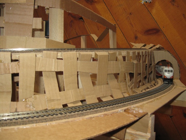
Here are a few shots of the wrapping in progress, plus a shot of what it looks like on the inside. The nice thing is it is completely hollow, and the I-beam framework makes all of it open on the bottom, so access is easy. Given that the armature is all carboard and plaster gauze, you can cut holes or what have you with an exacto knife or dremel wherever and whenever needed.
▔▔▔▔▔▔▔▔▔▔▔▔▔▔▔▔▔▔▔▔▔▔▔▔
When the going gets weird, the weird turn pro. -- HST
1uffakind.com/robots/povBitMapBuilder.php
1uffakind.com/robots/resistorLadder.php
▔▔▔▔▔▔▔▔▔▔▔▔▔▔▔▔▔▔▔▔▔▔▔▔
··Thanks for any·
·
·
·
·
Sam