

Anybody see anything dumb in this (Input on my design)
 photomankc
Posts: 943
photomankc
Posts: 943
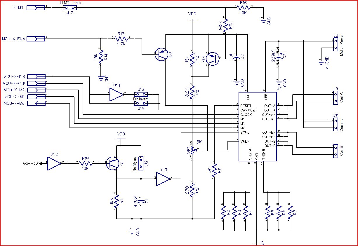
I'm working on interfacing a Prop with 3 SLA7062 chips for a 3 axis, 40V, 3A,·unipolar CNC drive.· The idea will be to make each axis driver a plug in board so the whole kit isn't scrap if an axis blows.· The datasheet indicates that the SLA logic side can just operate on 3.3V so I was hoping to keep it all 3v instead of 5V.··So the·compromise I made is not using MOSFETs since I haven't got any on hand·that·will switch fully on·with a 3V gate.· I doubt the tiny currents involved here would hurt one in it's linear region but I was not sure.· I also had plenty of PNP transistors on hand to experiment with but no P-Channel MOSFETs·so I just used used them.· I just want to make sure I am not doing anything fundamentally dumb here with those.·
Q1 turns off the SYNC input whenever an incoming CLK input is dected and keeps it off for a couple microseconds past the falling edge.· Q2 forces the chip to sleep by pulling the VRef input·above 2V·when ENA is low.· Q3·allows for idle current limiting.· It cuts the VRef in half (roughly)·by·switching in·the 15K resistor·to raise the upper section of the divider.· This drops the current trip point for the·SLA's chopper and thus the max current to the motor.· Breadboard seems to bear these all out testing them but they are not connected to the real chip yet.· I need to make a breakout for it.
I'm thinking it would be a good idea to fuse the motor power to something above·5A to prevent a short from burning up the expensive driver·chip.· Anything else anyone can see I'm missing here?
Fire away!·
1226 x 843 - 132K
Comments
to inhibit back EMF just fyi.
I am at the moment working with a g540 gecko driver. Cool thing it has is it uses 10x microstepping but it changes to full stepping on the fly.
I talked with one of the programmers at gecko about how that is done since the chip can not tell the future how can it know when to switch to full stepping and keep the timing right.
Basically since you must have a ramp up and ramp down and both are the same you know there are x number of steps to ramp back down so once the frequency gets over a fixed point you can switch from say 16 to 8 to 4 to 1/2 to full step on the fly making higher speeds even at high microstepping settings.
Just brought that up since you are doing the control modual, may be intersting to try.
One downside to the gecko 10 microstep version is the computer i am using is only a 600mhz so I can only go 25khz on the port driver, that limits me to 150IPM on my 5TPI ballscrews but that is fast enough to get me going.
▔▔▔▔▔▔▔▔▔▔▔▔▔▔▔▔▔▔▔▔▔▔▔▔
Think Inside the box first and if that doesn't work..
Re-arrange what's inside the box then...
Think outside the BOX!
I have an idea I want to try for microstep morphing with this one.· Since the Mo output indicates when the motor is one of the 45* positions I should be able to shift up the microstep setting at those points and skip the appropriate number of input steps to keep in sync.· As long as I shift only at those points I·should be sending the motor to the correct position·by always waiting for the pulses·to accumulate before sending and never shifting until I reach one of those 45* positions which are the same postion in the table in all the microstep modes.
That's for after the basic functions are working.· Right now my PASM is fast enough to track with a 200KHz input pulse rate but that will change if I add the morphing.· Probably would top out at 150KHz if I need another 50 to 70 instructions to get it done.· For stand alone control I plan to allow a keyboard to be attached.· I can then run simple stand-alone power-drive control too.· I plan to have an LCD to track the position based on steps so you can use it like a DRO as long as the movement is done through the controller and not manually.· The PASM driver can already keep it's position to a relative zero.
http://www.st.com/stonline/products/families/motor_control/dspin.htm?wt.mc_id=enews_dec09_dspin
I have some TI 8811's but they are teensy tiny and I can't solder them unless I buy a breakout board. That is a nice bipolar chip as well
▔▔▔▔▔▔▔▔▔▔▔▔▔▔▔▔▔▔▔▔▔▔▔▔
Think Inside the box first and if that doesn't work..
Re-arrange what's inside the box then...
Think outside the BOX!