

Making a PCB for a Luxeon Rebel RGB +W Matrix, any thoughts on improvement?
 OakGraphics
Posts: 202
OakGraphics
Posts: 202
Howdy gang,
I am making a lumileds Rebel RGB +W LED matrix to be run by Jon Williams DMX-IO board, and thought of trying my hand at doing this on a PCB.
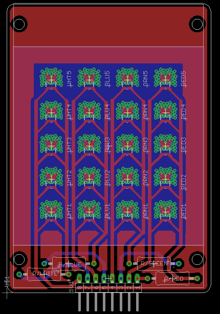
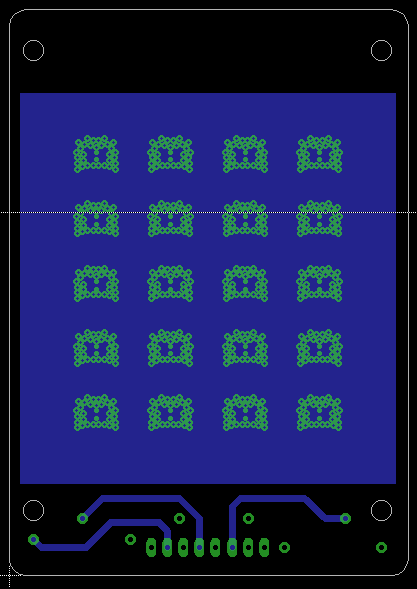
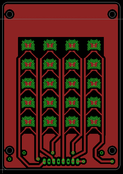
Here is what it looks like currently:
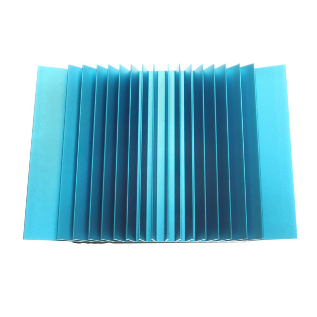
The back of the unit will have a heatsink on it from digikey ( part ATS1379-ND). I have thought of a beefier heatsink with perhaps a fan but I probably need to so some experiments on what is the right size.
Each line will use 350ma X 5 for 1.75 amps @ 3.10VDC which is a little hotter then the DMX-IO board was configured for so I will have to beef up that board a bit.
There is a 'ground plane' on the front but it is floating currently. There is also a 'thermal plane' on the back that mates directly to the heatsink. The heatsink is thermal tape applied currently. each power run is 40 mils thick with the end-runs down to 27mils - which apparently is the recommendation from luxeon. I probably could be more creative and bring the 40 mils right to the SMT pad but was wondering if that would cause problems during the soldering phase.
I am not totally convinced I want to run these in parallal, and I am thinking of re-doing the circuit to make it a serial run instead. This should even out any current-draw issues that national semiconductors tends to talk about in their webench page.
Anywho - any suggestions? What ya think?
I am making a lumileds Rebel RGB +W LED matrix to be run by Jon Williams DMX-IO board, and thought of trying my hand at doing this on a PCB.
Here is what it looks like currently:
The back of the unit will have a heatsink on it from digikey ( part ATS1379-ND). I have thought of a beefier heatsink with perhaps a fan but I probably need to so some experiments on what is the right size.
Each line will use 350ma X 5 for 1.75 amps @ 3.10VDC which is a little hotter then the DMX-IO board was configured for so I will have to beef up that board a bit.
There is a 'ground plane' on the front but it is floating currently. There is also a 'thermal plane' on the back that mates directly to the heatsink. The heatsink is thermal tape applied currently. each power run is 40 mils thick with the end-runs down to 27mils - which apparently is the recommendation from luxeon. I probably could be more creative and bring the 40 mils right to the SMT pad but was wondering if that would cause problems during the soldering phase.
I am not totally convinced I want to run these in parallal, and I am thinking of re-doing the circuit to make it a serial run instead. This should even out any current-draw issues that national semiconductors tends to talk about in their webench page.
Anywho - any suggestions? What ya think?
430 x 614 - 41K
417 x 589 - 26K
417 x 588 - 33K
640 x 640 - 75K
Comments
Leon
▔▔▔▔▔▔▔▔▔▔▔▔▔▔▔▔▔▔▔▔▔▔▔▔
Amateur radio callsign: G1HSM
Yeah - I have followed the Application Brief AB32 which gives the layout and such for the pcb. I am certainly not crowding the LEDs as they can be as close as 4mm to each other with that pattern, but I wanted to disperse the heat more with the back heatsink. I am using the Open via FRB-4 for pcb design as I don't know how to make the closed and capped via solution they mentioned, which would give better performance for heat dissipation, but I figure the back heatsink should help significantly.