Stupid Question - How to read a Datasheet?
Okay everyone, I apologize for the incredibly stupid and probably off-topic question. . .but I have a question pertaining to my Stamp 2 Rocket Project, but this is a problem I have all the time. Basically I order a part from Mouser (or wherever), I get it. . .and then I open up the Datasheet as a reference as I'm wiring up a project. BUT, in many cases, I wind up discovering that there are many different "versions" of a particular component, and I haven't the slightest idea how to figure out what "version" I have in my hand.
Take this example:
1) I ordered an MPX4115A pressure sensor from Mauser
2) I want to get it wired up, and before I wire up anything, I want to try to understand how it should work
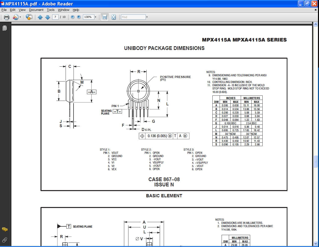
3) Open the datasheet and discover that I have a "unibody" model
4) Determine that there are three styles of the "unibody" model with TOTALLY different wiring
5) Note with some fear that voltage inputs are different pins on different styles, and some have reverse poliarity!! Danger!
Apparently I can't upload the datasheet, but I've attached a screen capture of the page in question. There is another chart on the first page, that seems to support this being a "style 1", but it's confusing as all get-out to have what appears to me to be contradicting wiring instructions!
I would also expect that simply supplying 5v to Pin3 and grounding Pin2 would yield a variable voltage on Pin1. . .but it doesn't. . .It just shows a voltage of 4.06v continuously, so reading the value with an ADC isn't working.
Any inputs, suggestions on either question would be much appreciated. Thanks!
-Jeff


Comments
▔▔▔▔▔▔▔▔▔▔▔▔▔▔▔▔▔▔▔▔▔▔▔▔
Powered by enthusiasm
http://www.freescale.com/files/sensors/doc/data_sheet/MPX4115A.pdf
The parts came in a static foil bag, with a standard warning sticker. . .they was nothing on the bag.
-Jeff
It sounds like you did make the connections as per the first page, ground to pin 2, V+ to pin 3 and Vout from pin 1, and you found Vout=~4 instead of the Vout=~0.25 expected at atmospheric pressure. Are you sure about the connections, sensor not backwards, ground connection firm?
▔▔▔▔▔▔▔▔▔▔▔▔▔▔▔▔▔▔▔▔▔▔▔▔
Tracy Allen
www.emesystems.com
Thanks, and I'm glad that it made you look twice too. . .I've blown up so many different components I try REALLY hard to study up before hooking things up! What I actually discovered is that the readings I'm getting from the MLX41151A are actually accurate. . .Apparently the voltage goes down as the pressure decreases, so it's higher at lower altitudes. Now the reading makes more sense to me, and my testing shows that everything is working. Thanks!
-Jeff
▔▔▔▔▔▔▔▔▔▔▔▔▔▔▔▔▔▔▔▔▔▔▔▔
Tracy Allen
www.emesystems.com
-Jeff