

AD5220 controlling PWM with 555 and BS2
 Campeck
Posts: 111
Campeck
Posts: 111
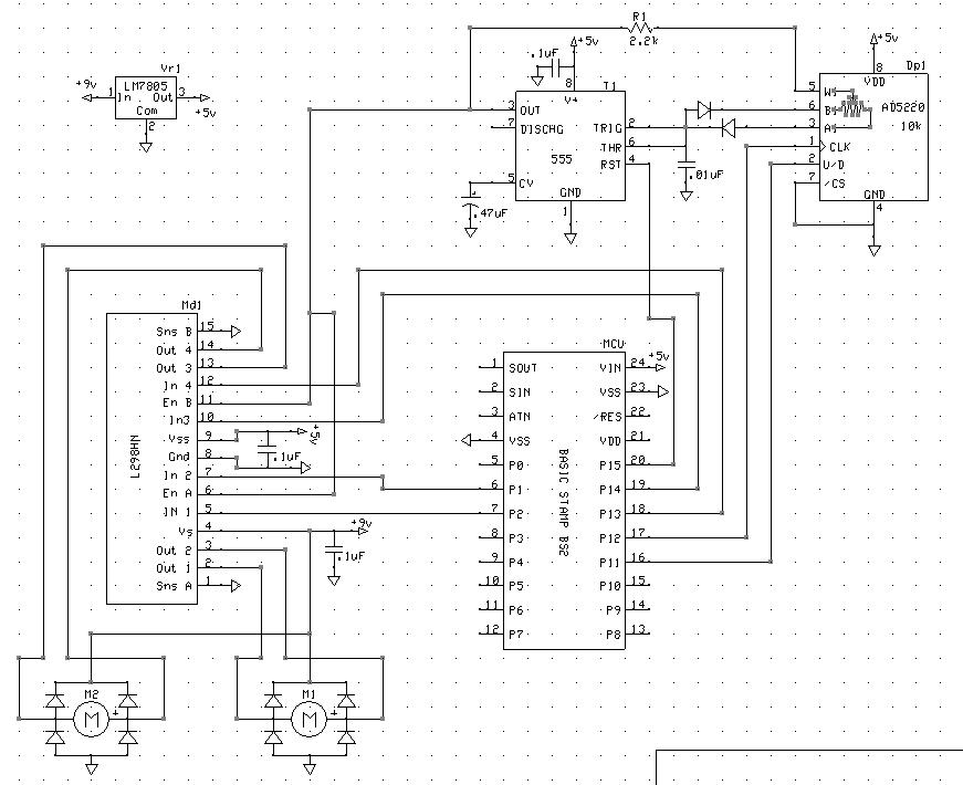
Here is a schematic of My "Tank-Bot" It uses a 555 and AD5220 as a BS2 controlled PWM circuit to send clock pulses to the enable inputs of an L298 dual H-bridge motor driver.
At the beginning of the program I reset the AD5220 to the A position which results in an almost 0% duty cycle. Using this little bit of code.
Then using this code...
This works fine with the motors accelerating smoothly as the resistance of the ad5220 from W1 to B1 decreases and the duty cycle increases.
Then the motors slowing down as the opposite happens.
Problem is when I run the below pre-programmed type code It acts erratically speeding up to full speed at random times or slowing down.
Batteries are fresh and the bug seems to have no real pattern. If I redo the program right after it may show different symptoms or none at all.
I think I may need a large capacitor across the power lines of select chips to prevent the motors turning on at speed 10 from a stop possibly overloading the MCU....idk.
Anyone spot any obvious problems?
Thanks!
Post Edited (Campeck) : 12/6/2009 8:42:36 PM GMT
At the beginning of the program I reset the AD5220 to the A position which results in an almost 0% duty cycle. Using this little bit of code.
HIGH UD                              'move wiper toward A side
PWM CLK, 255, 127
Then using this code...
' What's a Microcontroller - DigitalPotUpDown.bs2
' Sweep digital pot through values.

' {$STAMP BS2}
' {$PBASIC 2.5}

'-----------------------------------VARIABLES

counter VAR Byte

'-------------------------------DEFINE OUTS DIRS------------------

OUTS = %0000000000000000
DIRS = %1111111000100110

'----------------------------------------RESET AD5220-------------------------

HIGH 11                              'move wiper toward A side
PWM 12, 255, 127                'apply 127 position changing clock pulses

'This program resets the AD5220 to the full A side for 0% duty cycle. then goes from tap 0 of the ad5220 and makes its way up to tap 127
moving one tap every 10ms or so. Therefore increasing motor speed. Then it counts down.

'-----------------------INITIALIZE MOTOR DIRECTION---------------------------------------------

OUTS = %1100000000000010           'bit 15 = 555 control, bit 14 = left track forward, bit 1 = right track forward.

'------------------------------ACCELERATE----------------------------

DO
  LOW 11                                     'set wiper to move toward B side of ad5220.
  FOR counter = 0 TO 127              'count from 0 to 127
    PWM 12, 255, 1                          'pulse CLK pin of ad5220 1 time then
    PAUSE 10                                  'then wait 10 ms
  NEXT

'------------------------------DECELERATE--------------------------------------

  HIGH 11                                  'set wiper to move toward A side of ad5220
  FOR counter = 127 TO 0                 ' count down from 127
    PWM 12, 255, 1                          'pulse CLK pin of ad5220 1 time then
    PAUSE 10                                  'then wait 10 ms
  NEXT

LOOP
This works fine with the motors accelerating smoothly as the resistance of the ad5220 from W1 to B1 decreases and the duty cycle increases.
Then the motors slowing down as the opposite happens.
Problem is when I run the below pre-programmed type code It acts erratically speeding up to full speed at random times or slowing down.
Batteries are fresh and the bug seems to have no real pattern. If I redo the program right after it may show different symptoms or none at all.
I think I may need a large capacitor across the power lines of select chips to prevent the motors turning on at speed 10 from a stop possibly overloading the MCU....idk.
' {$STAMP BS2}
' {$PBASIC 2.5}

OUTS = %0000000000000000
DIRS = %1111100000100110          'set all pins with wires attached in schematic to outputs.


' -----[noparse][[/noparse] Variables ]----------------------------------------------------------

address           VAR    Word                               ' Stores EEPROM address.
instruction        VAR    Word                           ' Stores EEPROM instruction.
DPold              VAR    Byte                           'store  digital pot position old         0 - 127
DPnew             VAR    Byte                         'store new position for digital pot.   0 - 127
DPset              VAR    Byte                           ' store calculated difference and apply pulse to ad5220
newspeed        VAR    Nib                            ' store value 0 - 10 as pulled from EEPROM by instruction
oldspeed          VAR    Nib                           'store old valuse of 0 - 10

UD               PIN   11
CLK              PIN   12
_555             PIN   15
SPKR             PIN    5

' -----[noparse][[/noparse] EEPROM Data ]--------------------------------------------------------

DATA  5,"FFPBBP",6,"FFPBBP",7,"FFPBBP",8,"FFPBBP",9,"FFPBBP" ,10,"FFPBBPQ"           ' Navigation instructions.

' -----[noparse][[/noparse] Initialization ]-----------------------------------------------------

HIGH UD                              'move wiper toward A side
PWM CLK, 255, 127

FREQOUT SPKR,200,3200
FREQOUT SPKR,200,3700
FREQOUT SPKR,200,4200
PAUSE 2500

' -----[noparse][[/noparse] Main Routine ]-------------------------------------------------------
'This program looks in the DATA and if Its a number it compares it to the last number and scales the numbers to 0-127 from 0 - 10
'and then gets the difference which it pulses to the AD5220 Which changes the duty cycle of the PWM of the 555. With this setup
' The tank can not make sweeping turns. A future design will have two 100k digital pots controlling a 556 for the two tracks. I burned up one
'AD5220 by using a 220ohm resistor on the AD5220 W1 input instead of a 2.2k , Which caused 20 mA to flow through something rated at no more than 5. oops.
'If the DATA is a Letter it sees which routine to call. And each routine turns the corresponding direction control pins on the L298 chip on.

DO UNTIL (instruction = "Q")

  READ address, instruction                    ' Data at address in instruction.
  address = address + 1                       ' Add 1 to address for next read.


  SELECT instruction                           ' Call a different subroutine
    CASE "F": GOSUB Forward                    ' for each possible character
    CASE "B": GOSUB Backward                   ' that can be fetched from
    CASE "L": GOSUB Left_Turn                  ' EEPROM.
    CASE "R": GOSUB Right_Turn
    CASE "N": GOSUB BRight_Turn
    CASE "V": GOSUB BLeft_Turn
    CASE "P": GOSUB pause_
    CASE 0 TO 10: GOSUB speed
  ENDSELECT

LOOP

DIRS = %0000000000000000
END                                            ' Stop executing until reset.

' -----[noparse][[/noparse] Subroutine - Forward ]-----------------------------------------------

Forward:
OUTS = %1100000000000010                       ' Forward subroutine.
  PAUSE 500
RETURN
' -----[noparse][[/noparse] Subroutine - Backward ]----------------------------------------------

Backward:
OUTS = %1010000000000100                       ' Backward subroutine.
PAUSE 500
RETURN                                         ' Return to Main Routine loop.

' -----[noparse][[/noparse] Subroutine - Left_Turn ]---------------------------------------------

Left_Turn:
OUTS = %1000000000000010                        ' Left turn subroutine.
PAUSE 500
RETURN                                          ' Return to Main Routine loop.

' -----[noparse][[/noparse] Subroutine – Right_Turn ]--------------------------------------------

Right_Turn:
OUTS = %1100000000000000                        ' right turn subroutine.
PAUSE 500
RETURN                                          ' Return to Main Routine section.

' -----[noparse][[/noparse] Subroutine – BRight_turn ]--------------------------------------------

BRight_Turn:
OUTS = %1000000000000100                        ' right turn subroutine.
PAUSE 500
RETURN                                          ' Return to Main Routine section.

' -----[noparse][[/noparse] Subroutine - BLeft_Turn ]---------------------------------------------

BLeft_Turn:
OUTS = %1010000000000000                        ' Left turn subroutine.
PAUSE 500
RETURN                                          ' Return to Main Routine loop.

'------------------------------------------------------------------------------

pause_:

OUTS = %0000000000000000
PAUSE 1000
RETURN

'---------------------------------------------------------------

speed:

 LOW _555                                       'turn off 555 for speed calculations

 newspeed = instruction                           ' save 0 -10 value of instruction to newspeed
 DPnew = newspeed */3270                      ' scale 0 - 10 to 0 -127
 DPold = oldspeed */3270                         'scale 0 - 10 to 0 -127

 IF (DPnew) > (DPold) THEN                   'figure out which one is bigger
    DPset = DPnew - DPold                     ' find difference and save value
    LOW UD                                          'set wiper to move toward B side to increase duty cycle
    PWM CLK, 255, DPset                       ' apply # of pulses to CLK pin of AD5220
    oldspeed = newspeed                       ' save value of newspeed as oldspeed


 ELSEIF (DPold) > (DPnew) THEN                  'figure out which one is bigger
    DPset = DPold - DPnew                              ' find difference and save value
    HIGH UD                                              'set wiper to move toward A side to decrease duty cycle
    PWM CLK, 255, DPset                         ' apply # of pulses to CLK pin of AD5220
    oldspeed = newspeed                            ' save value of newspeed as oldspeed

  ELSE                                             'else do nothing
  ENDIF

RETURN
Anyone spot any obvious problems?
Thanks!
Post Edited (Campeck) : 12/6/2009 8:42:36 PM GMT

Comments
Post Edited (PJ Allen) : 12/8/2009 1:15:45 PM GMT
Let me try that....
I'm not too sure what going on. But all my code isn't showing up in the folder I put it in. when I look for it with the attachment manager or with file explorer. But the stamp editor shows all of them.
Post Edited (Campeck) : 12/8/2009 6:48:29 PM GMT
I remember reading that the PWM command isn't a true Squarewave with a dutycycle. But a highspeed stream of 0's and 1's
That over the time period equals the duty cycle.
So I was wondering if this was affecting the AD5220 in that it wasn't seeing a clean pulse with the PWM command.
Which I had put in in favor of a FOR...NEXT loop.
But With this new speed calculation code preliminary checks indicate the code is clean of bugs.
speed:


 newspeed = instruction
 DPnew = newspeed */ 3270


 IF DPnew > DPold THEN
    LOW UD
    FOR counter = DPold TO DPnew
      PULSOUT CLK, 1
    NEXT
    DPold = DPnew


 ELSEIF DPold > DPnew THEN
    HIGH UD
    FOR counter = DPnew TO DPold
      PULSOUT CLK, 1
    NEXT
    DPold = DPnew

  ENDIF

RETURN
Post Edited (Campeck) : 12/9/2009 7:39:18 AM GMT