Stand Alone Basic Stamp Logic Analyzer (BSLA) - updated schematic
Hi All,
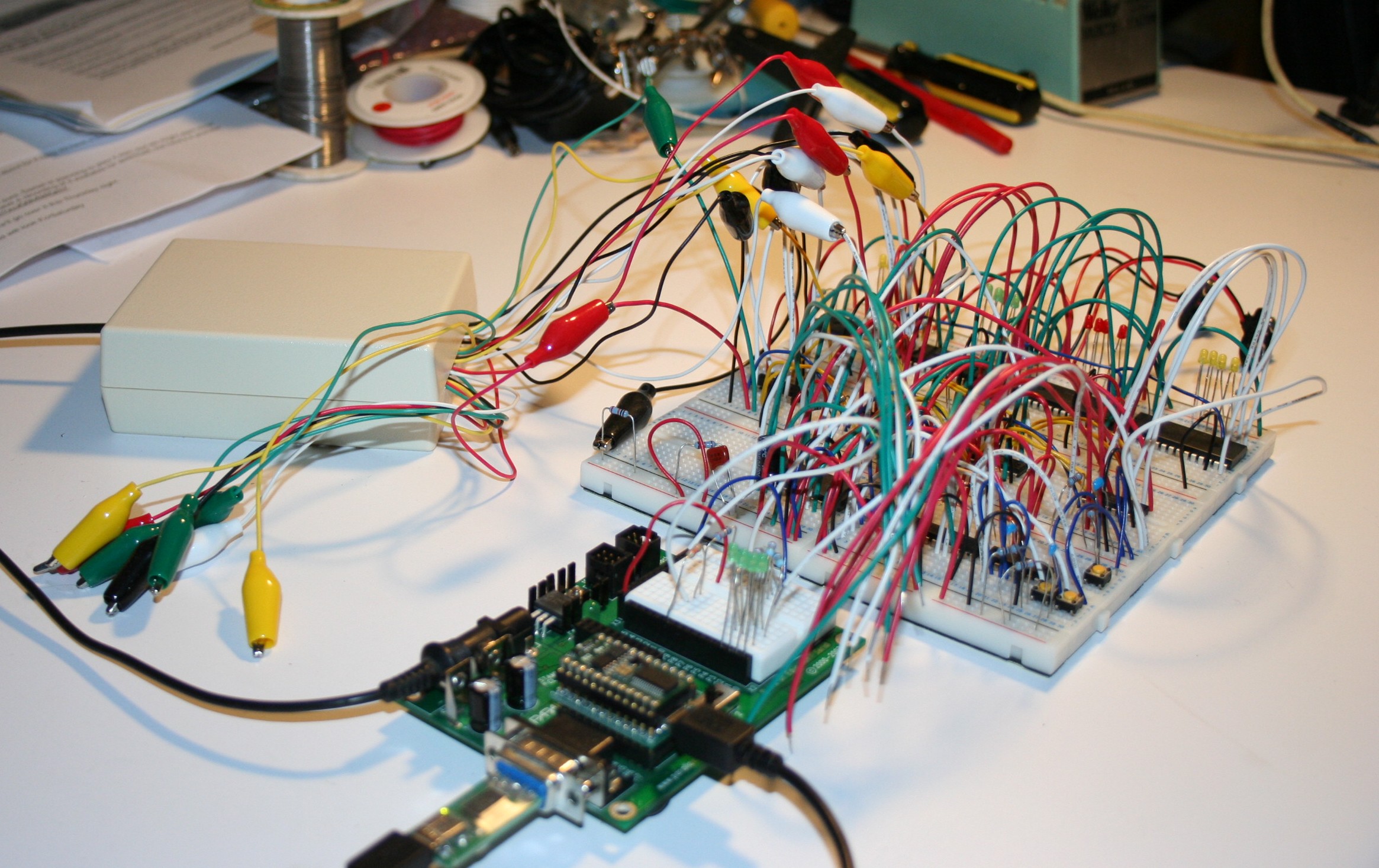
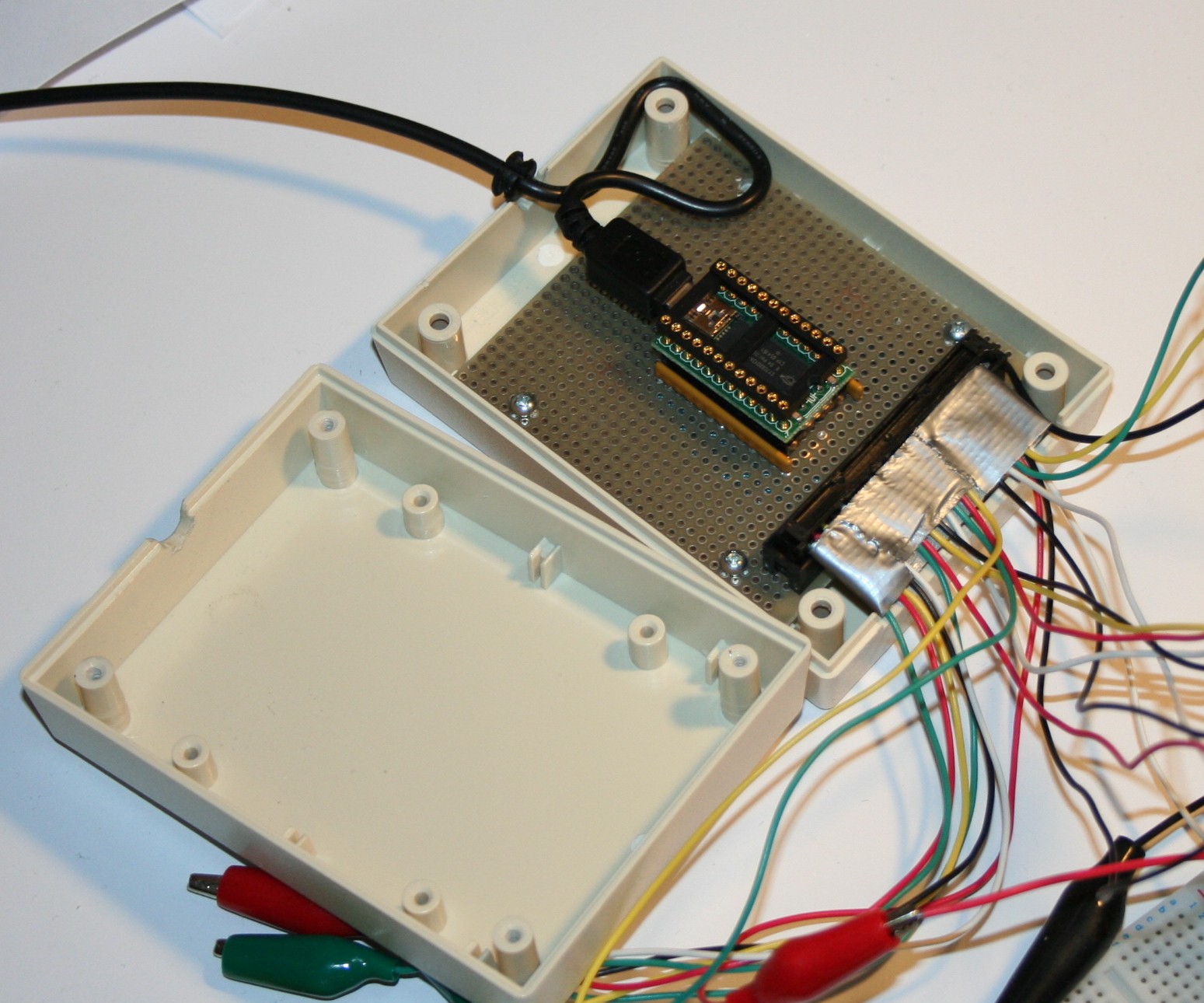
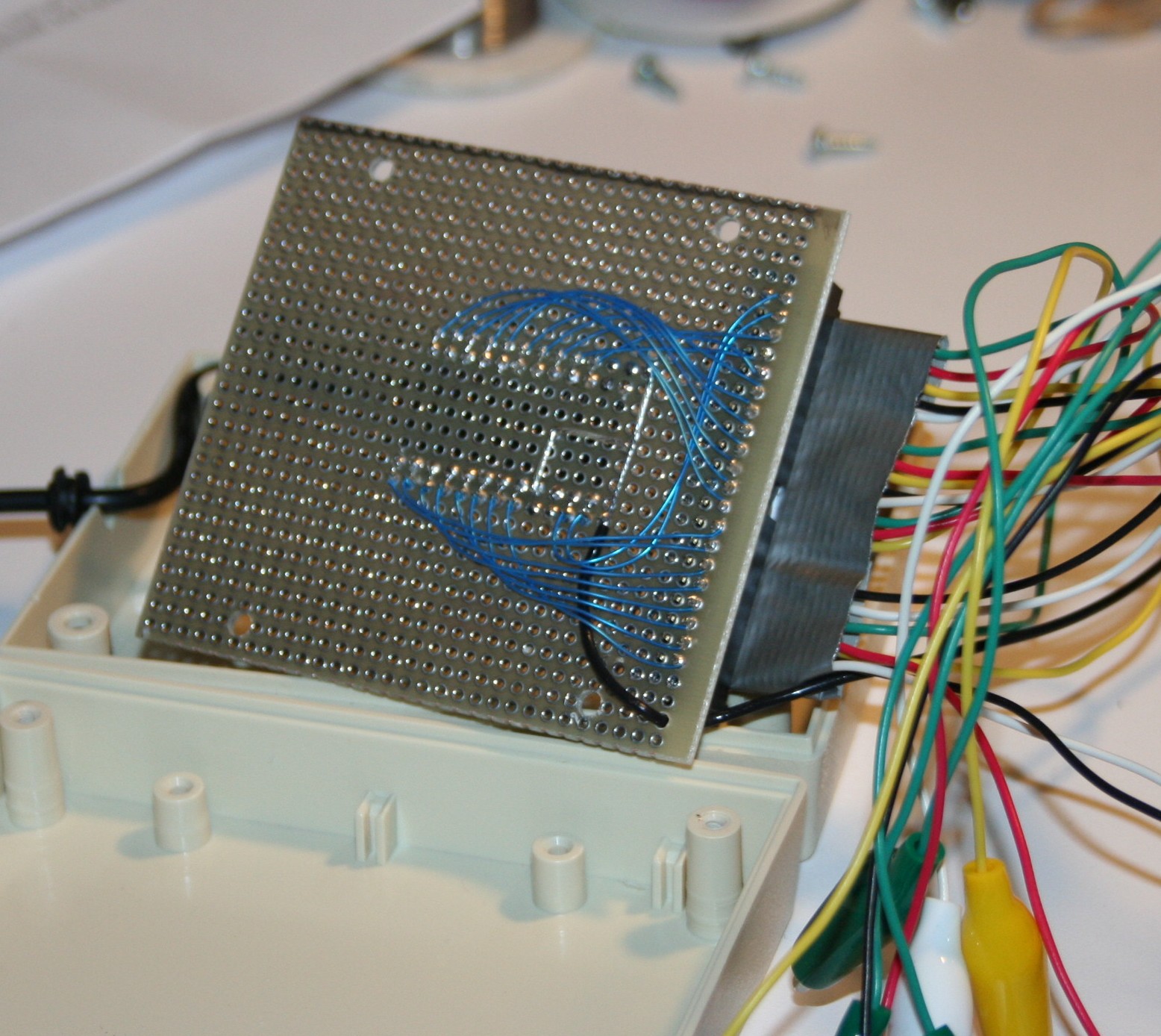
I needed·a low-cost logic analyzer to help with my current project.· Hearing about (and then verifying) the ability of the Parallax BSLA to be used by itself, not in conjunction with a Basic Stamp, I went about packaging the BSLA into a pod of sorts (see "cropped" pics).
All was well and good in terms of operation and usefulness.
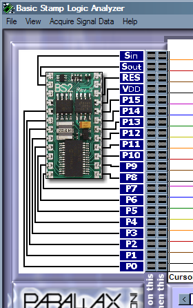
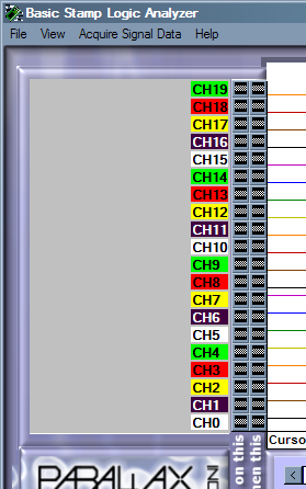
However, I was stuck with the BSLA GUI that includes an image of a Basic Stamp and its pin names.· Would it be possible to somehow modify the BSLA application to allow a different image and pin names?· Both primary resources said "no".· *8(
An InterWeb search, though, revealed someone who had recently gone throught the same effort as I...and he being a Windows level programmer was able to "hack" the BSLA app and "inject" his own image and pin names (see "ThatWasThen" and "ThisIsNow" pics).
For those interested in having this flexibility, go to: http://www.dlwrr.com/electronics/tools/bsla/hack/
Later,
DJ
▔▔▔▔▔▔▔▔▔▔▔▔▔▔▔▔▔▔▔▔▔▔▔▔
Post Edited (davejames) : 1/13/2010 6:15:47 AM GMT


Comments
Thanks for the kind words.
A note...the leads were originally 14" long with clips on both ends (pack of 10 gave me 20 leads). I cut them in half and then wedged the cut ends into a 40-pin flat ribbon connector. Then I used that old standby, duct tape, to reenforce the clips at the connector end.
The 'heart of the matter' was the work done by the other gentleman. A very inovative solution, I must say!
I'm kinda hoping that increased interest in the BSLA might prod Parallax to resurrect the product. The reason it was dropped was due to insufficient sales. It is beyond my comprehension why users didn't snap these little guys up; it has been invaluable in my debug efforts.
DJ
▔▔▔▔▔▔▔▔▔▔▔▔▔▔▔▔▔▔▔▔▔▔▔▔
Instead of:
"Those who can, do.· Those who can't, teach." (Shaw)
I prefer:
"Those who know, do.· Those who understand, teach." (Aristotle)
·
DJ
***Updated schematic posted two messages down***
▔▔▔▔▔▔▔▔▔▔▔▔▔▔▔▔▔▔▔▔▔▔▔▔
Post Edited (davejames) : 1/13/2010 5:13:41 PM GMT
▔▔▔▔▔▔▔▔▔▔▔▔▔▔▔▔▔▔▔▔▔▔▔▔
Chris Savage
Parallax Engineering
50 72 6F 6A 65 63 74 20 53 69 74 65
·
Well - somehow I blew 2 channels on the stand-alone BSLA.· After researching the part used (CY7C68013A), I found that the inputs have a maximum 5.25V limit...and I must have exceeded that.· Or, I buggered it with ESD.· Whatever.
In pestering Parallax and CWAV I found that the CY part is programmed on startup of the BSLA GUI, and that replacing the chip (Mouser, ~$14) could very well cure the issue.· So that avenue is open for the future.
In the meantime, I will be adding input protection on each channel.· This will consist of two series 100 ohm resistors and a couple of small signal clamp diodes (see attached updated schematic).· I'm hoping this won't degrade the performance of the unit; we use similar protection circuitry on 20MHz signal lines in equipment at work.
Regards,
DJ
▔▔▔▔▔▔▔▔▔▔▔▔▔▔▔▔▔▔▔▔▔▔▔▔
Post Edited (davejames) : 1/13/2010 5:11:39 PM GMT
If you exceeded 5V you definitely could have damaged the I/O pins. They weren't intended for any signal higher than a BASIC Stamp uses. On the other hand I disagree with what you were told about the programming. The code for the chip is not provided by the Application but rather through the development software. At least what goes on the EEPROM. Without that code the device shows up as a blank USB chip with an unprogrammed EEPROM.
▔▔▔▔▔▔▔▔▔▔▔▔▔▔▔▔▔▔▔▔▔▔▔▔
Chris Savage
Parallax Engineering
Check out the new Savage Circuits TV!
·
I actually suspect ESD more the culprit than exceeding the max input voltage; my app doesn't have more than 5.25V floating around. Either case, the +5V on the clamp diodes should protect against excessive levels.
RE: what I was told about the CY chip...
"The CY7C68013A does not need programming. You should be able to replace that chip and it will fix your issues.
All firmware is downloaded when you run the application."
As this was from "the horse's mouth", I would presume it's correct. I wasn't aware of the EEPROM on the BSLA so I see what you're saying. But if the EEPROM is intact, then replacing the CY chip should fix things? Yea/Nea?
Regards,
DJ
▔▔▔▔▔▔▔▔▔▔▔▔▔▔▔▔▔▔▔▔▔▔▔▔
I don't believe it is as simple as that. When we have unprogrammed modules we have a special application to reprogram them, otherwise the app doesn't recognize the BSLA. The special application is really core files and the firmware from the development software. But you can always try it and see what happens. I always tell people, you don't have to take my word for it. Try it for yourself and see.
▔▔▔▔▔▔▔▔▔▔▔▔▔▔▔▔▔▔▔▔▔▔▔▔
Chris Savage
Parallax Engineering
Check out the new Savage Circuits TV!
·
1) I'd guess sales were low because the intersection of Basic Stamp customers (newbie experimenters?) and those who need Logic Analysis (a more complex subject) is probably pretty slim. And the BSLA is pretty difficult to use outside of a BS2 without the hacked UI.
2) Also note that the BSLA's Sin and Sout are looking for RS232 levels, not TTL, so if you try to monitor TTL with those two channels you'll think they're "broken". At one point I had a schematic of the BSLA and it showed Sin and Sout connected to a max232 (or similar) which in turn is connected to the CY chip.
3) The BSLA is indeed a SUPER COOL product and it is a shame that its been discontinued.
Hi Dave - understood RE: Sin and Sout. My broken channels were "P2" and "P3".
DJ
▔▔▔▔▔▔▔▔▔▔▔▔▔▔▔▔▔▔▔▔▔▔▔▔
After the second time I used it I had·one pin break off·then the next time· I went use it two more pins broke off
I had spend this money on this and now 3 pins break off······ ·Now it is ·un use able···· ··Here is how I fix this Problem
I am sorry if you think that·I am taking over your post I do not mean too
When I saw what you did with your that gave an
One note the Pin Socket that· was on the board·was remove and replaced with a·Solider Tail·Rail Socket
▔▔▔▔▔▔▔▔▔▔▔▔▔▔▔▔▔▔▔▔▔▔▔▔
··Thanks for any·
·
·
·
·
Sam
Post Edited (sam_sam_sam) : 1/19/2010 10:31:54 PM GMT
My pins didn't actually break off - I evidently blew up the input circuits on P2 and P3; I suspect by ESD. Fortunately, all pins are structurally sound.
Later,
DJ
▔▔▔▔▔▔▔▔▔▔▔▔▔▔▔▔▔▔▔▔▔▔▔▔