

Would this work with a MAX 186 Chip Looking for Info and Feed Back if this wil
 sam_sam_sam
Posts: 2,286
sam_sam_sam
Posts: 2,286
Would this work or something like it

▔▔▔▔▔▔▔▔▔▔▔▔▔▔▔▔▔▔▔▔▔▔▔▔
··Thanks for any· ·that you may have and all of your time finding them
·
·
·
·
Sam
Post Edited (sam_sam_sam) : 11/26/2009 7:26:02 PM GMT
▔▔▔▔▔▔▔▔▔▔▔▔▔▔▔▔▔▔▔▔▔▔▔▔
··Thanks for any·
·that you may have and all of your time finding them ·
·
·
·
Sam
Post Edited (sam_sam_sam) : 11/26/2009 7:26:02 PM GMT
Comments
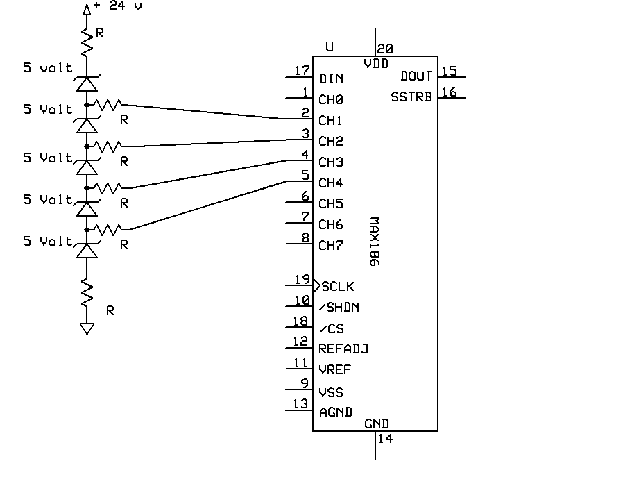
First, 5 5V zeners add up to more than 24V so the output voltages would be 0 or the result of leakage current only.
Second, the input voltage to the chip can only exceed the supply by 50mV, so even if the input voltage was higher (say 26V) so the zeners conducted all or most of the input voltages exceed the range of the ADC and would damage the chip unless the resistor to the input pin was high enough to limit the current to a value the protection diodes could handle.
What exactly are you trying to accomplish?
This what I want to is make Voltage latter that the max186 can read
0 to·12· one range in··· >>>>>>·· 1.25 steps
·then
12 to 24· second range· >>>>>··· ·1.25 steps
volts for a nicad charger
Do you have any ·
Thanks for any help that you can give me in this matter
▔▔▔▔▔▔▔▔▔▔▔▔▔▔▔▔▔▔▔▔▔▔▔▔
··Thanks for any·
·
·
·
·
Sam
Channel 0 would read 0-4096 for a 0 - 12V input (3mV per bit)
Channel 1 would read 0-4096 for a 12 - 24V input (3mV per bit)
The 50K pot could be adjusted to read 10mV per bit so the only math would be shifting the decimal and adding the 12V for the 12-24V range.
1.25 pre channel· stepping up to 10 volts· to 12 volts· Setting One
I want to charge 8 batteries in series and watch·each· battery's voltage·in each channel of the Max CHIP·and watch the·charging votlage and if
any channel gose above pre set value then slow charging rate so that voltage gose down to a safe value
2.50 pre channel· stepping up to 20 volts· Setting Two this is a maybe· because it would have··to watch two batteries at one time
▔▔▔▔▔▔▔▔▔▔▔▔▔▔▔▔▔▔▔▔▔▔▔▔
··Thanks for any·
·
·
·
·
Sam
Post Edited (sam_sam_sam) : 11/27/2009 2:58:23 AM GMT
The attached circuit should work. If you use the resistor values shown channels 3-5 readings need to be multiplied by 2, and channels 6-7 need to be multiplied by 3.
You could also substitute a zener diode for the 50K and 100K resistors. A 3.75-4V zener for the 50K and a 7.5-8V for the 100K. The readings for channels 3-7 would no longer need to be multiplied, but the zener voltage would have to be added to each channel.
I will give this try with the A··....>>>>> ·3.75-4V zener for the 50K and a 7.5-8V for the 100K. The readings for channels 3-7 would no longer need to be multiplied, but the zener voltage would have to be added to each channel.
Thank for your help in this matter
One note on the ICL board I am still working on that board
▔▔▔▔▔▔▔▔▔▔▔▔▔▔▔▔▔▔▔▔▔▔▔▔
··Thanks for any·
·
·
·
·
Sam