

Oscillation detection over 8,000 ft.
 IRobot2
Posts: 164
IRobot2
Posts: 164
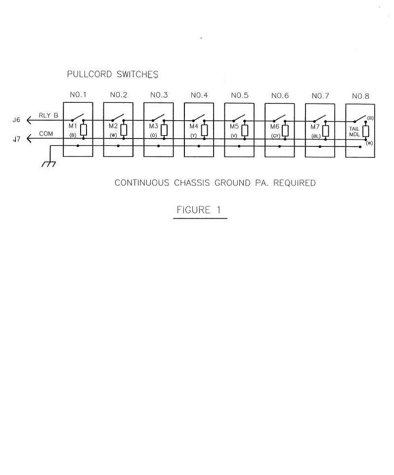
I am trying to recreate a Pullcord Monitor that has been discontinued and I plan on simplifying the circuit using a Prop. The operation is pretty simple. It has a main unit with (8) seven segment displays and two wires (+24vDC) running down a coal beltline. Every 1,000ft there is a safety stop switch. Whenever a switch is hit, it turns on an oscillator which tells the main head unit to light up the corresponding seven segment display to show which stop switch has been tripped (1 – 8).
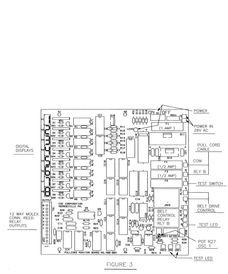
I have attached some diagrams of the unit, to illustrate what is going on.
Getting to my question: Do you think that these oscillator units are putting out a frequency which is matched to the main board (Fig 1) through filtering ICs? Or maybe some type of tone generation / tone detection circuit like DTFM? Since the end oscillator unit will be well over 8 thousand feet away I am unsure if any form of signal would be recognizable when it gets back to the main unit.
Any thoughts of what type of transmission is being used here (or a better way of doing it)?
▔▔▔▔▔▔▔▔▔▔▔▔▔▔▔▔▔▔▔▔▔▔▔▔
Alex Burke
"Beware of computer programmers that carry screwdrivers." -Leonard Brandwein
797 x 960 - 83K
801 x 960 - 231K
Comments
Are you replacing the pull switches and monitor or just the monitor?
If you are keeping the oscillators and just want to measure the frequency you could measure the time between zero crossings.
Another option would be to have a 555 timer at each switch location, each set to put out a different pulse width, and measuring the pulse width to determine the station that was activated. Each "pulser" would require a circuit with a voltage regulator, 555 timer circuit, and drive transistor.
CANbus could do all this as each node has its own binary address for response plus 8 bytes of data to indicate status (you really don't need so much).
Also, it has solid failsafe features that would be able to indicate if any node is down or taken off line (a very nice added feature) at any time.
The MCP2151 and MCP2551 chip set will work with any SPI interface - including the Propeller, the SX chips, or the Basic Stamp. You could still have the Propeller be the master unit, but Microchip makes other programmable CANbus chips that might be the simplest set up for each shut off station as they are nearly everything in one chip. Futurelec.com has some demo CANbus boards that are quite reasonable, but you would have to reprogram to your own use.
Admittedly, CANbus is a bit of learning curve to get into; but it is used in automotive braking systems and Airbuses fly by wire control and has an excellent safety record.
The master unit can poll all the slave units every 50 milliseconds to or so be assured that everything is up and running. The slave units will reply quite quickly. If no reply is received, the master would notify the operator and/or could automatically shut down the line. And the only wire required for signal is one very low voltage (no fire hazard) twisted pair. Of course, you would have to also provide +5 regulated VDC to each unit, but that power could be included in a 4 wire cable as a higher voltage and then regulated at each station.
The fact that CANbus is so cheap might allow you to easily double or triple the stations so that someone doesn't have to run as far to reach one. In fact, you could easily have 128 stations if you so desired.
▔▔▔▔▔▔▔▔▔▔▔▔▔▔▔▔▔▔▔▔▔▔▔▔
Ain't gadetry a wonderful thing?
aka G. Herzog [noparse][[/noparse] 黃鶴 ] in Taiwan
@Kwinn - I am having to replace the whole operation, oscillators and monitoring unit. I don’t even have a working model in front of me. I guess they went to purchase one and found out it does not exist any more. So it got passed to me to make one.
I do have a little more background on the unit now. I found out that no matter what cable is ran between each stop switch it acts the same. I mean, if a piece of cable gets cut and it is replaced with a much larger piece it still works the same. This tells me that this circuit is probably not based on resistance, nor any specific cabling. One more note. Each oscillator unit is given a specific number which is pared to the same number on monitoring unit (I know this seems obvious but figured I would state it). So if oscillator 2 and 3 get switched and I hit the second switch in line… #3 light will display any way. So there is for sure some type of data or signal.
@Byteloose – I am really going to have to look into CANbus. This is sounding like something that could work out for this project really well. One question though, how far (length) can data be sent down a wire before it is distorted? I know that nice square waves tend to flatten out and can start looking like other transmissions over long distance. Will this be an issue?
Oh, and one last note. It seems that the whole string of units is only run by two wires (3 if you count an extra ground which some states require for mining). It is just 24vdc. The oscillators simply transmit when the switch is closed… so I am assuming whatever data is sent back is via the common wire… right? Seems weird to me. I am stuck with the mindset of power, ground and signal.
▔▔▔▔▔▔▔▔▔▔▔▔▔▔▔▔▔▔▔▔▔▔▔▔
Alex Burke
"Beware of computer programmers that carry screwdrivers." -Leonard Brandwein
The diagram shows the switches and (perhaps) a resistor? Also, is there any chance the switches are closed in normal operation?
Then, I could see that the controller oscillator would be adjusted to see the "normal" amount of resistance. If any switch opened, or any cable got cut or shorted the controller would see the diffierence. This would be done with a classic "window detector" either in hardware or with a programmable device. And, as you've pointed out, there would be the possibilty of calculating where the actuated switch was located.
Just thinking out loud.
Cheers,
▔▔▔▔▔▔▔▔▔▔▔▔▔▔▔▔▔▔▔▔▔▔▔▔
Tom Sisk
http://www.siskconsult.com
·
The simplest would be to have a constant current source at each pull station. Each station would put a different current (1-10mA, 2-20mA, ...8-80mA) on the 2 wires that power them. A transistor, zener diode, and resistor is all that is required for each station. The current would be measured by the master console and the station number displayed.
Next step up in complexity would be the DTMF encoder/decoder. Each station would have a DTMF tone generator chip and associated circuitry and produces 2 tones to indicate station number. Station number could be set by a dip switch or jumper. The master console would have the tone decoder chip to decode the number from the 2 tones and display it.
The most complex would be some form of serial bus such as canbus or a simpler serial bus. I would suggest a simple serial current loop running at slow speed (100 bits/second). The station could be a small microcontroller that sends serial data by turning a constant current source on/off in order to send the station address. The protocol could be as simple as sending the address continuously only when the switch is closed, or have each station send its address and the status of the switch in turn on a continuous basis. This can all be done with 2 wires.
Two questions: 1- What is the approximate guage of the wire? 2 - Is the belt line out in the open, enclosed, or in the mine?
While I am not an expert on Safety Codes in Mines (Did someone say this was in a mine?), or Can Bus,
an 8,000 foot conveyer is still a major safety concern.
If your circuit is intended to be an Emergency Stop circuit then some sort of fail safe circuit/system ·needs to be included.
If the wire to one of the switches is cut, that switch will not work and you wont know about it until someone tries to stop the belt.
The advantage of the digital approach is that you can constantly monitor all the switches. If you wire the switches to be normally closed and open when activated, the circuit will catch broken wires along with defective switches.
You will need a microcontroller at each node, and this will cost more, but...
This will be much less than a lawsuit from a defective stop switch. (Remind the bosses about this when they groan about the cost)
The master can interrogate the switch stations many times a second, and sense in real time when a Switch/Station·failure occurs.
Corrective action can then be taken.
Also an Emergency Stop Switch is diffrent than a Red Push Button.
It has to operate even if its contacts are welded shut.
Make sure it is rated as an Emergency Stop Operator.
I would also look at any·local/federal codes that also may apply to this application.
Good Luck,
▔▔▔▔▔▔▔▔▔▔▔▔▔▔▔▔▔▔▔▔▔▔▔▔
Alan Bradford ·N1YMQ
Plasma Technologies
Canaan NH 03741
www.plasmatechnologies.com
@Alan – The idea of having a fail safe is very true. It only takes one small thing (like an e stop not working or a broken wire) to really hurt or kill some one. If there is any thing I can do to make it any safer (even beyond the basic requirements) I will do so. The only real restriction that I have is that the one that I build has to be a direct replacement for the one that is broken. The switches that I am interfacing to are actually part of the machine and not easily changeable… well that is what I was told. Every thing has to be changeable in my mind… and I am sure changing the types of contacts on the bottom would be an easy fix. So norm open or norm closed would not be a big problem.
Sending continuous data (of some type) seems to be the way to go. Looking for an interruption in communication seems to be much safer and an all around better idea than only sending data when the switch is closed.
There have been many great ideas talked about here. I think my path is getting pretty clear. Still one thing is escaping me (google is no help on this either). How far can I send say, a typical serial data stream from prop to prop without some major error correcting software or the like? I know there are many things to factor in like type of wire and power and such. But let’s just say prop to prop using cat5 type cable. (assuming we do not have to worry about interference or such… just open field distance.) Any one know? I only really care for the reason that when I build this I am not easily going to be able to “test” it with 8 or 10 thousand ft of cable. I will have to be really confident that I can transmit data that far. Other wise this will be a big “oops” on my part.
Thanks every one for all of your help and ideas.
▔▔▔▔▔▔▔▔▔▔▔▔▔▔▔▔▔▔▔▔▔▔▔▔
Alex Burke
"Beware of computer programmers that carry screwdrivers." -Leonard Brandwein
▔▔▔▔▔▔▔▔▔▔▔▔▔▔▔▔▔▔▔▔▔▔▔▔
24 bit LCD Breakout Board coming soon. $21.99 has backlight driver and touch sensitive decoder.
Post Edited (mctrivia) : 11/29/2009 1:18:35 AM GMT
You need to know the resistivity of the wire and the allowable Voltage Drop. Ohms law will give you the max distance. There are more things to consider like EMI(almost eliminated by using twisted pair wire) and the square wave edge bleeding(fixable by slowing transmittion frequency) but to know your absolute max this is how to find.
Copper Wire Gauge Resistance per foot
4 .000292
6 .000465
8 .000739
10 .00118
12 .00187
14 .00297
16 .00473
18 .00751
20 .0119
22 .0190
24 .0302
26 .0480
28 .0764
▔▔▔▔▔▔▔▔▔▔▔▔▔▔▔▔▔▔▔▔▔▔▔▔
24 bit LCD Breakout Board coming soon. $21.99 has backlight driver and touch sensitive decoder.
Assuming each station draws 50mA, station1 would see about 16V, station2 - 9V, station 3 - 3V, and the rest almost nothing. Even if the last station was the only one drawing power it would only receive 8V from the 24V supply. There are ways around this problem. One is to use very low power devices at the stations, and another is to provide each station with a power supply.
The communications from the stations is not a problem. Each station can act as a repeater so the data only has to travel 1000M, which is easily done at low data rates.
Copper wire resistance table
AWG 10 12 14 16 18 20 22 24 26 28
Ohms/100M 0.669 1.06 1.69 2.68 4.27 6.82 10.8 17.2 27.3 43.4
I am working on the schematic for this project as we speak (and I will post it when done for whoever is interested). The only thing I am still wondering about is if I can send this “tone” back down the beltline on the common wire. It seems that the only wires coming out of the main control unit are power and ground.
Anyone see a problem with this? I wonder if multiple tones going down the same wire will obscure one another from being detected.
@Kwinn - I am trying to think my way through how I can implement what you said about using each station as a repeater. By using tones and only being able to generate one tone at a time, it makes that kind of difficult. Yet it is probably going to be necessary.
▔▔▔▔▔▔▔▔▔▔▔▔▔▔▔▔▔▔▔▔▔▔▔▔
Alex Burke
"Beware of computer programmers that carry screwdrivers." -Leonard Brandwein
The existing circuitry generated a tone whenever the emergency switch was closed to provide 24V one of the tone generators.
Only one tone generator was supposed to operate at any one time.
The tone generators operated over a wide voltage range.
The reason I conclude this is that if all the stations draw current all the time the ones at the far end from the 24V supply would get virtually no voltage. Even if the one at the far end was the only one turned on the voltage would have been pretty low there.
As I said in my earlier post the major problem is powering them, not sending/repeating the signal. If each station board had a prop it could easily handle the receiving/repeater functions. Only a buffer/driver chip would need to be added.
Could you run cat5/6 cable with the existing 2 wires and do you know what gauge of wire is used for the 24V?
Could you run cat5/6 cable and provide power (120/240VAC or 5/12/24VDC)at each station?
I suggest you take a look at the RS-485 specifications, even if you skip the CANbus. You could just use RS-232 type serial and have each node broadcast a unique identity to the master periodically (like every 50 millaseconds). If there is a emergency, the unit would just shift to a different RS-232 code. In one byte - four bits would allow 16 addresses and 16 coded status.
IMHO, Oscillators and various frequencies are adding an unnecessary dimension of complexity without much benefit. It may have been a legacy method, but it really isn't necessary in a digitial age. I had my CANbus set up with 100' of wire on a test bench and pushing data back and forth for many months with no error conditions.
While RS-232 type serial will work alone, Canbus has additional recognition of errors in transmission via CRC and the ability to request the repeat of any failed transmission (which might be due to environmental issues occasionally upsetting data packets). In other words, the failsafe features are well developed.
▔▔▔▔▔▔▔▔▔▔▔▔▔▔▔▔▔▔▔▔▔▔▔▔
Ain't gadetry a wonderful thing?
aka G. Herzog [noparse][[/noparse] 黃鶴 ] in Taiwan
@kwinn – I am being told that the two wire system that is in place has to remain (and the only power that will be available will be distributed from the main unit). I know this is stupid… I am sorry. I have no idea why it has to be like this and no one seems to have a real good answer for me. I am just following orders at this point. If I could throw a piece of cat5 down the line it would make this project a lot easier.
I agree that each unit is only supposed to be powered when it is tripped. However I am positive that all units have to be able to be tripped at the same time. This is for safety and few other reasons. I thought long and hard yesterday about sending data from prop to prop down the line and how I could do it. Yet the only “communication” I have is through the ground and I am trying to figure out if it could cause an issue with communication. Or for that matter how I would even go about doing it in the first place. If each unit was sending data to the main control box it would be inevitable that collisions would occur and little if any usable data would come out the other end. If they were all synced and they took turns sending data back it would be cheap and easy. I think by doing this type of structure I am dancing around something like Byteloose was talking about with CanBus.
What is really eating at me is that this has been done… efficiently… many years ago. So if they can do it, I should easily be able to recreate it. Either duplicating it or making it better. I am trying to get my hands on an old unit. Even if it is broke I can see exactly what they did then. I will eventually figure this out. I just want to make sure I don’t go into the overkill category.
▔▔▔▔▔▔▔▔▔▔▔▔▔▔▔▔▔▔▔▔▔▔▔▔
Alex Burke
"Beware of computer programmers that carry screwdrivers." -Leonard Brandwein
1 - One or two tones per station at a specific frequency for each station (probably what was being done in the original system).
2 - A "current loop" approach where each station communicates serial data by increasing the current to indicate a 1 bit.
3 - A high frequency "carrier signal" approach where the data is sent by modulating a high frequency carrier.
Number 1 has the advantage of simplicity, but lacks any way of monitoring station status. Status monitoring could possibly be added by having each station send it's tone(s) briefly once per time period, one station after the other.
Number 2 and 3 are more complex but offer better fault monitoring capabilities.
You can also implement a master slave communication (half-duplex):
- master
- outputs the power supply through a high side low-ohm shunt and·a mosfet switch
- monitor the current through the shunt for slave answers/msgs
- cut the power supply to slaves to transmit/initialise/request by togling line voltage
- slave
- have a backup capacitor (enuogh to survive the short power losses)
- transmit by changing the line current
- monitor the line voltage to receive/initialize/sync
- optionally can measure power loss time for incoming communication (eg. 100ms=0; 200ms=1)
- slave answers when addressed in two way comm or after defined time (each slave different) after receiving a sync pulse
Basic concept attached▔▔▔▔▔▔▔▔▔▔▔▔▔▔▔▔▔▔▔▔▔▔▔▔
· Propeller Object Exchange (last Publications / Updates);·· Vaati's custom search
Post Edited (dMajo) : 12/2/2009 11:29:50 AM GMT
If you look at the attached block diagram you can see that even using AWG 12 wire there will be a total of 21.2 ohms resistance between each pull station, and a total of 169.6 ohms between the master and the last station.
If each station draws 10mA then the last station would get around 16V. If the last station were to short the power supply an additional 9.4mA is the maximum additional current that could be drawn from the power supply. This would imply that a change from 80mA to 89.4mA would be the change from 0 to 1. Station 1 would see the smallest voltage change as a result of this current change since it has only 21.2 ohms resistance between it and the power supply. That means it would have an input signal of .199V to distinguish between 0 and 1. It might be possible, and communication would have to be half duplex.
A quick thought, and I havent had time to work out a circuit yet but.....
How about making the data also the power...
I dont know if you are limited to 24 Volts.. How about using 50 volts and and switch the polarity with the data signal.
You could use a filter to recover the data at each station, and then rectify and filter the 50 volt power (Or what is left of it at the end) and power your station.
Who says the power has to be 'Clean' or exactally 50/60 HZ.
Oh and another wild thought just popped into my little brain...
Just run data down the control cable and use a small belt off of one of the conveyor rollers to generate local power to charge a storage battery at each sation.
The conveyor drive system would never see the added load of 10 little generators.
▔▔▔▔▔▔▔▔▔▔▔▔▔▔▔▔▔▔▔▔▔▔▔▔
Alan Bradford ·N1YMQ
Plasma Technologies
Canaan NH 03741
www.plasmatechnologies.com
@Alex,
I was looking at at the prop specs and it looks like the steady state current requirement for each station could be brought down to 1 or 2mA per. That would make modulating the current to transmit data practical and the station and master circuitry relatively simple. A switching regulator, prop, comparator, transistor, and a few passive components are all that is required.
Communications is half duplex and received by all devices connected to the power lines. Block diagram attached.
2 reasons. 1 the switching regulator will not draw constant current. 2 the constant current you are talking about will be likely less then your regulator will be drawing.
here is how I would do it.
run 24V DC on the line. Each station has a diode and series resister and large cap. this will keep the devices from trying to draw to much current and give them a energy resevoir for when they need large current supply. you then use a switching regulator to drop voltage to 3.3V to run the prop.
Every 10 seconds each device emits a small burst signal(0.1s) to show it is still there. Should a pull station be pulled the signal is will go on for 2sec then start alternating on/off every sec. signal is alternating to keep power draw down.
Now the question is what signal to use. Take a look at how DTMF actually works. it uses 2 frequencies that are not even multiples of each other so simple filters can tell them apart. If you used f=697*(1+2n) for each stations frequency(where n is station number 0 to 7) then even if all stations where on you could distinguish what stations are transmitting.
▔▔▔▔▔▔▔▔▔▔▔▔▔▔▔▔▔▔▔▔▔▔▔▔
24 bit LCD Breakout Board now in. $21.99 has backlight driver and touch sensitive decoder.
▔▔▔▔▔▔▔▔▔▔▔▔▔▔▔▔▔▔▔▔▔▔▔▔
· Propeller Object Exchange (last Publications / Updates);·· Vaati's custom search
http://www.conspec.com.au/Products/pull_cord_monitor.html
Cheers,
▔▔▔▔▔▔▔▔▔▔▔▔▔▔▔▔▔▔▔▔▔▔▔▔
Tom Sisk
http://www.siskconsult.com
·
▔▔▔▔▔▔▔▔▔▔▔▔▔▔▔▔▔▔▔▔▔▔▔▔
Alex Burke
"Beware of computer programmers that carry screwdrivers." -Leonard Brandwein
Post Edited (IRobot2) : 12/2/2009 3:37:25 PM GMT
As I wondered out loud in an earlier post, I think the oscillator is at the head end unit. Each switch station adds a known resistance so its fairly easy to figure the combined resistance. Suppose each resistor was 10K. Ignoring the cable resistance for the moment, having 32 stations would show up as 10000/32 = 312 ohms , having ten stations would be 10000/10 = 1000 ohms and so on. These resistance values change the oscillation frequency of the head end controller. Probably a phase-lock loop comparator detects when the frequency changes due to a switch opening, a cable shorting, etc.
Anyway, there are probably some economies to not having to have multiple conductors or individual power supplies down the line.
Tom Sisk
▔▔▔▔▔▔▔▔▔▔▔▔▔▔▔▔▔▔▔▔▔▔▔▔
Tom Sisk
http://www.siskconsult.com
·
I am now convinced that building a better system using the prop is possible. If you plan to go ahead I would be happy to help out in whatever way I can.
@mctrivia
You may very well be correct about needing a series resistor between the diode and capacitor. The capacitor acts as a reservoir for when transmitting a 1 causes the voltage on the power/common lines to drop, not because the prop circuitry draws extra power. The switching regulator runs at a much higher frequency than the baud rate I was planning to use so the chance of interference is low. I was also planning on the prop drawing 1-2mA at 3.3V, so the draw from the 16-24V available should be much lower than that.
I was planning to send the data as serial bits (slave # and status) rather than tones to avoid the need for filters.
@dMajo
I am building on 2 wires because that is what is available. A second pair for data would have made this much easier.
It is the slaves that have to report their status to the master. Having the master communicate with the slaves is not required, but is a simple and useful thing to have.
I agree that current loop is the best for this task. The difficulty comes from having that current added to the current that powers the slaves. Combine that with the fact that each slave will see a different change in voltage for a 1 bit and designing a generic slave board gets tricky. The alternative is to have different component values on the slave board dependent on its location on the belt. Something I am trying to avoid.
@Alan Bradford
Alan, since the entire system is being replaced I see no reason to be limited to 24V. I was thinking of increasing the voltage and adding a series resistor to increase the signal levels for my own approach.
Do keep in mind it is the slaves that have to report their status to the master. Having the master communicate with the slaves is not required, but is useful to have.
I am not sure I understood exactly what you had in mind but I am intrigued by your idea. Can you post or PM a simple diagram and explanation?
1) Isn't this design based on 2 wires?
2) Slave have to detect power/comm line voltage (but not small change) if present or not (so big change; in order of 10 or more volts) to detect data/sync from master.
3) When transmitting slaves have to modulate power/comm line current; no voltages here to detect.
4) Master receive by monitoring the power/comm line curent (through a shunt resistor). Master can optionally adjust shunt value if this is replaced by a mosfet (self calibrating). Current changes above 4mA can rapresent 1. Data is manchester encoded to be self cloking.
Extended concept (maybe more clear) added
▔▔▔▔▔▔▔▔▔▔▔▔▔▔▔▔▔▔▔▔▔▔▔▔
· Propeller Object Exchange (last Publications / Updates);·· Vaati's custom search
So here is my plan. I am making what I think is close to the “original” 8 station unit to start off with. I think we came to a consensus that it was based on tone. I know we said this was highly inferior but it will be a good replica to start from. I have two nice little circuits for tone generation (stations) and a decoder circuit (Main unit). Instead of using a speaker, it will be following the ground wire and instead of the 7 segment display I will put in a prop which can then delegate what happens to the signal (to 7segments or LCD.. relays… whatever).
I am going in this order of trial.
1. Tone generation and detection (using DTMF)
2. Frequency generation and detection (using narrow band pass filters)
3. Current detection
4. Power modulation
Like I said, #1 I have a general idea of how to do the tone circuit. #2 I still have to learn how to tune in the bandpass filters (little op amp circuits). #3 Seems increasingly difficult but I will give it a try. #4 Though it could work, I do not even know where to start.
Once I am able to at least get something working, I can spend all the time I want making it better. Even if that means going an entirely different direction. I think that the prop is capable of making this project pretty interesting and bringing this 1970’s -80’s unit up to date.
Let me know what you think of the two circuits (I do not have the power circuit or anything of the like on there. I just pulled these off the net. ) I am trying to make an actual schematic this morning. If anyone thinks I am building these out of order or am missing something or whatever, please let me know.
Thanks again for every ones ideas. I like how every one sees this a little different. I am still not sold on any one idea and I am very open to hearing why one is better than the other. Some of these sound great, I just do not fully understand. I will try and give each one a go and we can see exactly how each one turns out.
▔▔▔▔▔▔▔▔▔▔▔▔▔▔▔▔▔▔▔▔▔▔▔▔
Alex Burke
"Beware of computer programmers that carry screwdrivers." -Leonard Brandwein
It is indeed a 2 wire design. I do not recall seeing the slaves in your original post, but that may have been due to the problems I have been having with my internet connection recently.
@Alex,
Since all of these are intended to run off the power/common wires they are all a form of power modulation.
The tone decoders normally include digital filtering so this method basically includes #2. Get a data sheet for the 5089 to verify that a dip switch to ground works for that chip. Normally the row/column is used to scan for a key closure that connects one row to one column. If that is the case a dip switch can still be used but the common side is not grounded. It is left floating so that closing one row switch and one column switch will select the pair of tones to send.
I have attached the datasheets for the 5089 (and the 8870). It is used in a matrix style going to ground. But I think if we use a dip to isolate the ones that we don't want, we can use the estop switch to break ground and that will be what generates the signal. Come to think of it I don't think we need the dip switch at all. What do you think of this circuit? Simple enough... but will it work for our purposes?
BTW I have finally got an answer about the cable. It is 12awg and we can have up to 28vdc on the line. If that helps out any at all.
▔▔▔▔▔▔▔▔▔▔▔▔▔▔▔▔▔▔▔▔▔▔▔▔
Alex Burke
"Beware of computer programmers that carry screwdrivers." -Leonard Brandwein