Help programming a Pic 12f675
 W9GFO
Posts: 4,010
I'm working on a project where I need the Pic to read a servo pulse and then output a high or low depending on what that pulse value is. I would think that it would be a very simple program.
Last night I dug out my PicKit 1 (never used it) and downloaded the MPlab IDE. I expected that with a few years worth of experience using Basic Stamps and the Propeller chip that I would be able to muddle my way through this Pic thing. Not so.
Then I spend a couple hours searching the interwebs for a good tutorial. I find lots of info but it none of it is what I am looking for. I just need a sample program (in Basic or C) so that I can understand how to put together my own code.
A while back someone offered to help with Pic programming but I can't remember who that was. I really don't want to have to join another forum for something so simple when I know that there are many here that can help. That would be like telling someone to join a semiconductor forum when they have a question about a diode.
I really wish Parallax made a single cog, 8 pin, < 1$ Propeller chip. Then I wouldn't have to turn to MicroChip.
Rich H
▔▔▔▔▔▔▔▔▔▔▔▔▔▔▔▔▔▔▔▔▔▔▔▔
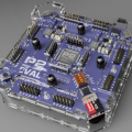
The Simple Servo Tester, a kit from Gadget Gangster.


Comments
▔▔▔▔▔▔▔▔▔▔▔▔▔▔▔▔▔▔▔▔▔▔▔▔
Mike2545
This message sent to you on 100% recycled electrons.
;flasher.asm
;simple program for PIC12F675 to flash LED on pin 5
;uses Timer0 for delay

    list      p=12f675    ;list directive to define processor
    #include "p12f675.inc"    ;processor specific variable definitions

;-----------------------------------------------------------------
;defines
;-----------------------------------------------------------------

    #define LED 2    ;GP2 (pin 5)
    #define INIT_COUNT 10    ;


;-----------------------------------------------------------------
;variables
;-----------------------------------------------------------------
    cblock    0x20
    Shadow
    tick_counter
    endc

;------------------------------------------------------------------
;initialisation
;------------------------------------------------------------------

    ;reset vector
    org    0
    goto    Main

    ;interrupt vector
    org    4
    banksel    INTCON
    bcf        INTCON,T0IF        ;clear Timer0 interrupt flag
    movlw    INIT_COUNT        ;re-initialise count
    movwf    TMR0
    decf    tick_counter,f
    retfie

Main:
    banksel ANSEL
    movlw     11h           ;AN0 as analog input,conversion clock Fosc/8
    movwf     ANSEL
    bankseL    CMCON
    movlw     07h            ;comparators off
    movwf     CMCON
    banksel    TRISIO
    bcf        TRISIO,LED    ;LED output GPIO5 (pin 2)
    banksel    OPTION_REG
    movlw    b'00000011'        ;prescaler 1/128
    movwf    OPTION_REG        ;
    banksel    TMR0
    movlw    INIT_COUNT        ;initialise timer count value
    clrf    tick_counter
    movwf    TMR0
    bsf        INTCON,GIE        ;enable global interrupt
    bsf        INTCON,T0IE        ;enable Timer0 interrupt
    banksel    GPIO

;-----------------------------------------------------------------------
;main program loop
;-----------------------------------------------------------------------

;loop:
;    bsf        Shadow,LED    ;LED off
;    movfw    Shadow
;    movwf    GPIO
;    call    dly
;    bcf        Shadow,LED    ;LED off
;    movfw    Shadow
;    movwf    GPIO
;    call    dly
;    goto    loop


loop:
    bsf        GPIO,LED
    call    dly
    bcf        GPIO,LED
    call    dly
    goto    loop


dly:
    movlw    0x10
    movwf    tick_counter
dly1:
    movf    tick_counter,f
    skpz
    goto    dly1
    return

    end
I can let you have the MPLAB project directory, if that helps.
Read-Modify-Write isn't a problem with this program because of the delays, but I've included some commented-out code that uses a shadow register to avoid R-M-W effects.
73, Leon
▔▔▔▔▔▔▔▔▔▔▔▔▔▔▔▔▔▔▔▔▔▔▔▔
Amateur radio callsign: G1HSM
Post Edited (Leon) : 11/22/2009 9:00:37 PM GMT
-Phil
PICBasic looks to be a good fit for me - wish they had a trial version. Would I need to purchase a programmer as well or is there a way I can use MPLab to to get the compiled code into the chip?
Rich H
▔▔▔▔▔▔▔▔▔▔▔▔▔▔▔▔▔▔▔▔▔▔▔▔
The Simple Servo Tester, a kit from Gadget Gangster.
Leon
▔▔▔▔▔▔▔▔▔▔▔▔▔▔▔▔▔▔▔▔▔▔▔▔
Amateur radio callsign: G1HSM
▔▔▔▔▔▔▔▔▔▔▔▔▔▔▔▔▔▔▔▔▔▔▔▔
Mike2545
This message sent to you on 100% recycled electrons.
I have found Proton PicBasic Lite which seems very similar to the MeLabs PicBasic and it does support the 12f675 - the PicBasic Pro demo does not.
I'm geting closer, Proton's PicBasis is supposed to be accessible from within MPlab, I'll see if I can get it to work soon.
I requested some AtTiny 13a samples to see how I get along with those but for now I want to see if I can use these 12f675s.
Here is what I have so far, it compiles fine but I have yet to put it on a chip. I would be surprised if it worked - seems like there is configurations missing, ie., the XTal freq.
Device = 12F675

Dim Pulse As Byte

Symbol P0 = PORTB.0                         ' Define pulse input pin
Symbol P1 = PORTB.1

ALL_DIGITAL = True                            ' Set ports to digital mode


Main:


    GoSub ReadPulse
    If Pulse <  150 Then
    High P1
    Else Low P1
    EndIf
    GoTo Main


ReadPulse:  PulsIn P0, High, Pulse                                ' Read pulse width
            DelayMS 20
            Return
I'll replace the "GoTo" when I figure out the equivalent of a DO - LOOP.
Rich H
▔▔▔▔▔▔▔▔▔▔▔▔▔▔▔▔▔▔▔▔▔▔▔▔
The Simple Servo Tester, a kit from Gadget Gangster.