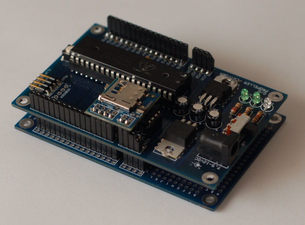
Now Available: uSD Card Module for Propeller Platform
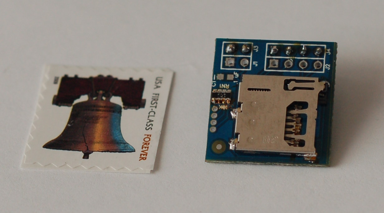
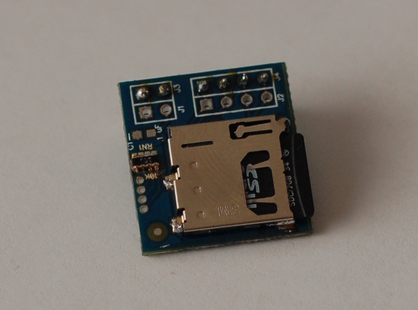
Been working on this guy for a little while - it's a really tiny microSD card adapter for the Propeller Platform, although it also works on a breadboard, protoboard, or anything else - it's smaller than a postage stamp and interfaces in SPI mode.
UPDATE - These are back in stock. They now use a slightly smaller uSD card slot so the pin functions can be written directly to the pcb;

Anyway - more info on the project page.
▔▔▔▔▔▔▔▔▔▔▔▔▔▔▔▔▔▔▔▔▔▔▔▔
Propeller Forums RSS Feed!
Gadget Gangster - Share your Electronic Projects
Post Edited (Nick McClick) : 3/21/2010 8:11:26 PM GMT
UPDATE - These are back in stock. They now use a slightly smaller uSD card slot so the pin functions can be written directly to the pcb;

Anyway - more info on the project page.
▔▔▔▔▔▔▔▔▔▔▔▔▔▔▔▔▔▔▔▔▔▔▔▔
Propeller Forums RSS Feed!
Gadget Gangster - Share your Electronic Projects
Post Edited (Nick McClick) : 3/21/2010 8:11:26 PM GMT


Comments
▔▔▔▔▔▔▔▔▔▔▔▔▔▔▔▔▔▔▔▔▔▔▔▔
Gadget Gangster - Share your Electronic Projects
How in the world did you solder those inside pins for the card slot? Did you just leave them bare?
Also as an added note. The item has pull up resistors on board. Nothing else is needed to use the unit.
James L
▔▔▔▔▔▔▔▔▔▔▔▔▔▔▔▔▔▔▔▔▔▔▔▔
James L
Partner/Designer
Lil Brother SMT Assembly Services
Are you addicted to technology or Micro-controllers..... then checkout the forums at Savage Circuits. Learn to build your own Gizmos!
Post Edited (James Long) : 11/10/2009 9:07:16 PM GMT
▔▔▔▔▔▔▔▔▔▔▔▔▔▔▔▔▔▔▔▔▔▔▔▔
Gadget Gangster - Share your Electronic Projects
For future reference, you only need it in the oven for about 6-8 minutes at that temp (using leaded solder). That is from starting cold.
Good idea though......Hope you are not eating from that oven....especially if you used leaded solder. If you did....you need to clean it top to bottom very thoroughly. Lead solder will vapor and coat the inside. Very dangerous stuff.
Not sure you would have done that, but I like to make sure.
Well....that tells me if testing is needed. I guess no testing for the design is needed, just functional checks.
James L
▔▔▔▔▔▔▔▔▔▔▔▔▔▔▔▔▔▔▔▔▔▔▔▔
James L
Partner/Designer
Lil Brother SMT Assembly Services
Are you addicted to technology or Micro-controllers..... then checkout the forums at Savage Circuits. Learn to build your own Gizmos!
From what I read - pin2 -- when connected to a card, is pulled high by the card.
Oak,
If that is the case, it won't work with the SPI mode. There are pull up resistors on the pins for the SPI mode......so the pins are always high.
I would have to talk to Lonesock or some of the other guru's to see if that could change for the uSD card.
James L
▔▔▔▔▔▔▔▔▔▔▔▔▔▔▔▔▔▔▔▔▔▔▔▔
James L
Partner/Designer
Lil Brother SMT Assembly Services
Are you addicted to technology or Micro-controllers..... then checkout the forums at Savage Circuits. Learn to build your own Gizmos!
JonnyMac,
To have the board over hang the lower module, it is used in the 28-31 position. It can also not over hang the board and use the 0-3 position.
The Pinout of the uSD is also in order of the of FRSW files if used in the 28-31 position, but backwards in the 0-3
James L
▔▔▔▔▔▔▔▔▔▔▔▔▔▔▔▔▔▔▔▔▔▔▔▔
James L
Partner/Designer
Lil Brother SMT Assembly Services
Are you addicted to technology or Micro-controllers..... then checkout the forums at Savage Circuits. Learn to build your own Gizmos!
Post Edited (James Long) : 11/11/2009 7:02:19 PM GMT
I am working on a "micro-microSD module" that will be less than 1/2" square. I am using a Molex uSD socket that retains just the end of the card (P/N 0473095251). I originally got them for my QFN based DIP40 module because the height of the uSD socket would allow the card to share the same real estate as the QFN, just a little above it. That project is a little behind, so I am making a handful tiny uSD modules just because I really like the sockets.
▔▔▔▔▔▔▔▔▔▔▔▔▔▔▔▔▔▔▔▔▔▔▔▔
Andrew Williams
WBA Consulting
WBA-TH1M Sensirion SHT11 Module
Special Olympics Polar Bear Plunge, Mar 20, 2010
There are different brands too. Some click in/click out like the big ones. Others (like Cluso's) just slide in.
Re pins - maybe it needs to stay flexible until a standard evolves. P0-3 is one standard. I used P12-P15 on a recent board. P28-31 would clash with a number of serial objects but there would be code workarounds.
uSD cards are about $10 and the ones I've bought come with an adaptor to go up to standard size. They seem compatable with all the existing code - 4 lines, 10k pullups on all the lines and 2 power pins.
I'm wondering, if the pin order is wrong for P0-P15, would it be possible to put the header in from the other side of the board and flip the sd board upside down? Or turn it around?
▔▔▔▔▔▔▔▔▔▔▔▔▔▔▔▔▔▔▔▔▔▔▔▔
www.smarthome.viviti.com/build
Post Edited (Dr_Acula) : 11/11/2009 11:20:34 PM GMT
Yes, you could flip the board and go that way. If you did it that way the board would over hang the module on the P0-P3 side. This has to do with the power pins and their layout.
You could also just rearrange the pinout in the object ( and save it with a different name), but that does take some understanding of what the object writer did. I had to do that with my first iteration of uSD connection. I didn't have it ordered the same as the FSRW guys did.
We didn't make this as flexible as some of the other uSD card slots. With the SPI type connection, the card can not be accessed other ways. We did this because most of the programming at this point is designed around the SPI mode.
If there is ever another way to access the uSD cards, will may redesign to a new version of board.
So there are options depending on how you put the connection header on. Just remember, the orientation of the board will change (over hang/ not over hang) depending on the way you want to use it.
James L
▔▔▔▔▔▔▔▔▔▔▔▔▔▔▔▔▔▔▔▔▔▔▔▔
James L
Partner/Designer
Lil Brother SMT Assembly Services
Are you addicted to technology or Micro-controllers..... then checkout the forums at Savage Circuits. Learn to build your own Gizmos!
▔▔▔▔▔▔▔▔▔▔▔▔▔▔▔▔▔▔▔▔▔▔▔▔
www.smarthome.viviti.com/build
I'm still learning about SD storage and the Prop, so I have to defer the technical questions, but it will fit on either side of the Propeller Platform. Of course, it'll also fit on breadboards, protoboards, or on anything else.
@Dracula - this is the locking type of slot. I'm not sure it really makes a difference in an implementation like this. I guess you would want a locking holder if it's going in your pocket. You can definitely flip the pins - it's a little harder to access the memory card, but otherwise works fine.
▔▔▔▔▔▔▔▔▔▔▔▔▔▔▔▔▔▔▔▔▔▔▔▔
Gadget Gangster - Share your Electronic Projects
@DR,
The board will have all surface mount parts already mounted. I'm not sure Nick's idea about the headers, but I am assuming the through hole soldering will be left to the end user.
This would allow the user to decide how he/she would like to use the board.
If I can get a camera, I will give all the options for the end user can choose from for using the board. The best method would to have extra long headers(top and bottom), where it could be used in either orientation, but I'm not sure how hard those are to find, nor how expensive they may be. The holes in the board do allow for both top and bottom headers, but this does depend on the device you are attaching to.
@Nick,
Let me know if you are having success. That will determine how I assemble these boards. If you are not able to confirm the correct operation of the board, I will need to check one from the first panel.
@ everyone
There will need to be some basic instructions for the board. Since there is little room for silkscreen, the board is not marked (at least I do not think it is). The instructions will need to label the pins for use.
James L
▔▔▔▔▔▔▔▔▔▔▔▔▔▔▔▔▔▔▔▔▔▔▔▔
James L
Partner/Designer
Lil Brother SMT Assembly Services
Are you addicted to technology or Micro-controllers..... then checkout the forums at Savage Circuits. Learn to build your own Gizmos!
I've tried a couple times to search the Parallax forums, and each time it comes up empty.
Jim
Here's the project page
and here's the instructable I did.
▔▔▔▔▔▔▔▔▔▔▔▔▔▔▔▔▔▔▔▔▔▔▔▔
Gadget Gangster - Share your Electronic Projects
▔▔▔▔▔▔▔▔▔▔▔▔▔▔▔▔▔▔▔▔▔▔▔▔
Propeller Forums RSS Feed!
Gadget Gangster - Share your Electronic Projects