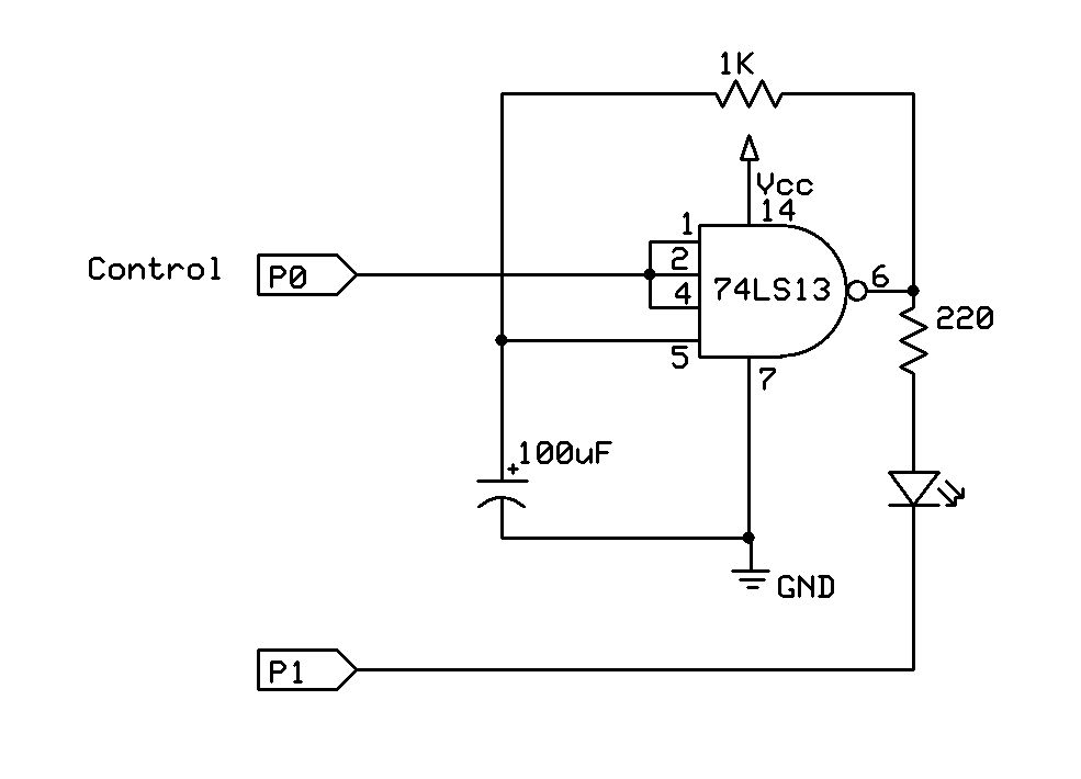
Three state LED - on, off, flashing
Hi All,
I need to have an LED go into one of three states (off, on, flashing), depending on the status of an input. I'm going to be doing other things during the main loop so I don't want to waste time with pause statements, so I was wondering if the attached circuit would do the trick. It's a modification of a two state led flasher from Forest Mims' Engineer's Notebook. It's based on a 74LS13 dual NAND Schmitt trigger, and according to the text, setting the control high will enable flashing and setting it low will keep the led on steady. Theoretically, if I set P1 low and P0 high it would enable the led to flash, if P0 is low the led would stay on, and if P1 is high it would turn it off. Would this work? Is there a better way to do it?
Post Edited (whyrnutz) : 11/9/2009 8:54:32 PM GMT


Comments
This (off-loading some tasks) is classic microprocessor design technique.
We do it with serial buffers, pwm control, high speed counters, etc.
· Please use a descriptive Subject!
Cheers,
▔▔▔▔▔▔▔▔▔▔▔▔▔▔▔▔▔▔▔▔▔▔▔▔
Tom Sisk
http://www.siskconsult.com
·
Thanks, Tom!
Tom Schoenknecht
no other circuit needed.
LOW 0 ' turns the LED off
HIGH 0 ' turns the LED on steady
INPUT 0 ' allows the LED to flash at the rate determined by R and C
Note that the CD4093 is a CMOS Schmitt trigger, and the circuit benefits from the high impedance CMOS input. Note that the resistor is a 1 megaOhm and the RC product is the same as it is in your circuit, 0.1 second, and it is the RC product that sets the flash rate. The high resistor value won't work with the 74LS series chips. There are CMOS triggers in the 74HC series (e.g. 74HC14, 74HC132).
▔▔▔▔▔▔▔▔▔▔▔▔▔▔▔▔▔▔▔▔▔▔▔▔
Tracy Allen
www.emesystems.com
Post Edited (Tracy Allen) : 11/8/2009 9:42:12 PM GMT
Holy smoke, I really learned something too, from Tracy's response. That's amazing - another thing I'd have bet couldn't be done.
now if you want cool tracy's idea is that!
I just wish I had been paying more attention when I wrote the original post as I didn't realize there was no subject until I saw it posted. I tried to go back and change it but it appears you can't do that. I'd really like to fix that as I'm sure there are other people who could benefit from this circuit. Speaking personally, I wish I had had this for many past projects, it would have made life much easier. Anyone have any thoughts? Is there a way to edit the subject line?
Yup - go back to your original post, press the "pencil button" in the upper right corner (you'll enter edit mode), and change the subject line there. Re-submit and you're done!
And Mr. Allen, very nicely done with that tip.
DJ
▔▔▔▔▔▔▔▔▔▔▔▔▔▔▔▔▔▔▔▔▔▔▔▔
Instead of:
"Those who can, do.· Those who can't, teach." (Shaw)
I prefer:
"Those who know, do.· Those who understand, teach." (Aristotle)
·
Tom
DJ
▔▔▔▔▔▔▔▔▔▔▔▔▔▔▔▔▔▔▔▔▔▔▔▔
Instead of:
"Those who can, do.· Those who can't, teach." (Shaw)
I prefer:
"Those who know, do.· Those who understand, teach." (Aristotle)
·
▔▔▔▔▔▔▔▔▔▔▔▔▔▔▔▔▔▔▔▔▔▔▔▔
Tracy Allen
www.emesystems.com
The 74HC14 is a personal favorite of mine.
▔▔▔▔▔▔▔▔▔▔▔▔▔▔▔▔▔▔▔▔▔▔▔▔
Beau Schwabe
IC Layout Engineer
Parallax, Inc.