

Dual-Axis analog Joystick Help.
 TheComputerCrew
Posts: 6
TheComputerCrew
Posts: 6
I am having trouble building a stable, high-resolution RC-Time circuit with this setup.

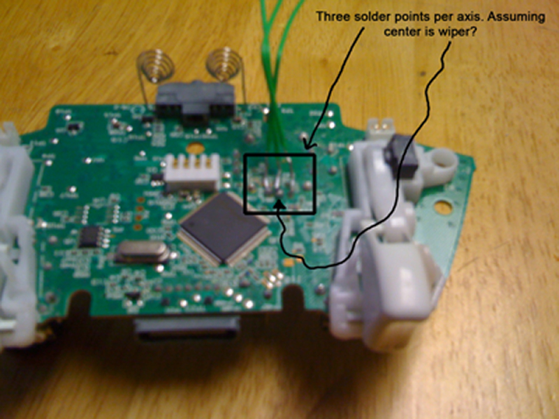
The PCB is out of an Xbox 360 wireless controller. The joystick has three solder points for each axis which I am assuming is similar to a dial potentiometer. I want to use this controller to power my robotics experiments. The wireless is proprietary and thus far, un-hackable. My goal here is to put together my own board with the original Xbox components (joysticks, tact switches, triggers, etc.) and have it fit back into the original controller case. Any help on utilizing these joysticks and other on-board components would be greatly appreciated.

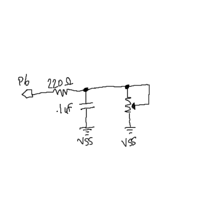
This is the schematic

The joystick is obviously spring auto return to center. When I tilt the joystick all the "left" I get an rc-time of 35000. Back at center is 61000. All the way "right" is just below 35000. How could I possible utilize these readings. WHat am I missing here? Thank in advance to all!
Post Edited (TheComputerCrew) : 11/7/2009 12:07:05 AM GMT
The PCB is out of an Xbox 360 wireless controller. The joystick has three solder points for each axis which I am assuming is similar to a dial potentiometer. I want to use this controller to power my robotics experiments. The wireless is proprietary and thus far, un-hackable. My goal here is to put together my own board with the original Xbox components (joysticks, tact switches, triggers, etc.) and have it fit back into the original controller case. Any help on utilizing these joysticks and other on-board components would be greatly appreciated.
This is the schematic
The joystick is obviously spring auto return to center. When I tilt the joystick all the "left" I get an rc-time of 35000. Back at center is 61000. All the way "right" is just below 35000. How could I possible utilize these readings. WHat am I missing here? Thank in advance to all!
Post Edited (TheComputerCrew) : 11/7/2009 12:07:05 AM GMT
Comments
▔▔▔▔▔▔▔▔▔▔▔▔▔▔▔▔▔▔▔▔▔▔▔▔
- Stephen
Yes sir, I am certain. It has one pot per axis and a z-axis tact switch. The black "box" on each axis rotates as you move the joystick. Also there are three solder points per pot.
Didn't even cross my mind, thank you.
Forgive my "newbieness", but what is RCTIME overflow and how can I correct this?
You fix this by not letting it happen by choosing a proper capacitor value. The Stamp Manual chapter on the RCTIME statement gives the formulas involved. You may need a small fixed resistor in series with the pot so that the total resistance has a minimum other than zero.
Post Edited (Mike Green) : 11/7/2009 4:03:02 PM GMT
An invaluable resource. Thank you for your time, sir.
First, thanks for everyone's responses.
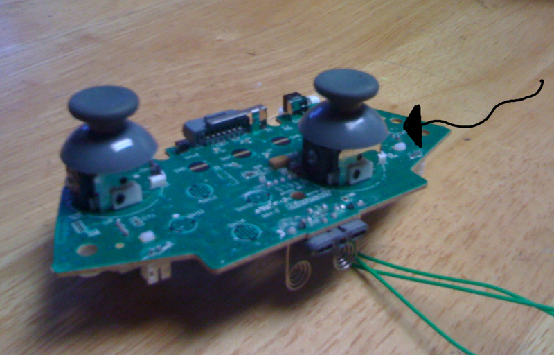
Next, I took Mikerocontroller's advice from post #3 and removed the joystick from the board. This was a success due to the fact that the PCB's circuitry was adulterating my pot readings.
After removing the joystick, a simple RCTIME circuit taken straight from the "What's a Microcontroller" text, page 151, did the trick. The only modifications to the circuit from the text were the substitution of the joystick for the rotating pot (obviously), and the substitution of a 100µf capacitor. This capacitor was able to give me readings (after scaling and offset) from 506 to 998. The readings before being modified by code were 17 and 632.
Also, I utilized the z-axis tact switch that is built into the lower portion of the xbox360 joystick. It worked very well.
Although very rudimentary and simple, this proves that I can utilize all the input devices off of this circuit board and integrate them onto a custom PCB that will fit back into the xbox360 controller. This will preserve the function of every button and switch as well as provide an implementation of this controller into robotics control. It would be much simpler to use the existing hardware, but, unfortunately, it doesn't look as though Microsoft's wireless encryption will be decoded anytime soon.
Thanks all!!
Post Edited (TheComputerCrew) : 11/11/2009 3:08:44 PM GMT