

Serial out vs shift out
 tedbeau
Posts: 48
tedbeau
Posts: 48
First off, sorry this is such a long post. I realize there are more than one or two issues here I need help with.
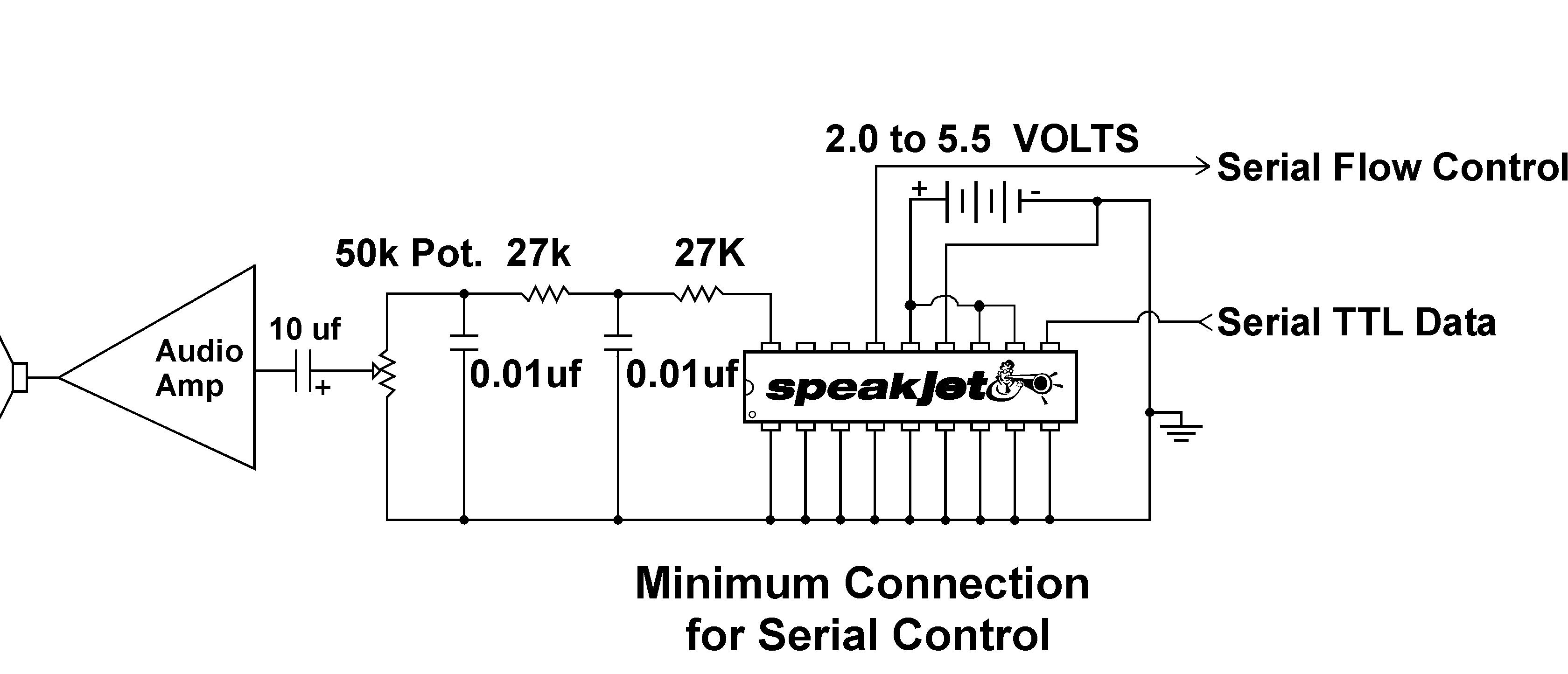
OK, I am working with·a speakjet chip and a bs2.
I have the circuit set up simular to what is shown in the manual for serial input.
http://www.magnevation.com/pdfs/speakjetusermanual.pdf
I think the circuit is OK, because when I power everything up and run the following program the speakjet speaks "Ready" as per the manual.
However I can not figure out how I am supposed to be sending the data to the speakjet. According to the manual;
"The SpeakJet can be controlled simultaneously by logic changes on any one of its eight Event Input lines, and/or by a Serial Data line from a CPU (such as the OOPic, Basic Stamp or PC) allowing for both CPUControlled and Stand-Alone operations. Other features include an internal 64 byte input buffer, Internal Programmable EEPROM, three programmable outputs, and direct user access to the internal five channel sound synthesizer.
And here is more info:
Serial Data is the main method of communicating with the SpeakJet to execute commands or create voices and sounds. The serial data can also be used to program the internal EEPROM. The SpeakJet does not accept actual RS-232A signal levels, and will be damaged if attempted to input these levels. In order to read data from a RS-232A type of serial data stream, a level shifter/line receiver must be used. This can be as simple as a small transistor or more robust device like the MAX232A from Maxim.
The SpeakJet serial configuration is fixed at: 8 bits, No- Parity, and 1 stop bit (8, N, 1) and non-inverted, (RS-232 is inverted logic and higher voltages). The Speakjet can be configured to accept Baud rates from 2400 to 19200. The factory default setting is 9600 baud. This baud rate can be changed any time by placing the SpeakJet into the "Baud Rate Configure Mode.
To verify that the SpeakJet was placed in serial control mode, the Acknowledge Commands Command "V" can be issued which causes the SpeakJet to enunciate the word "Ready"
Example: To place the SpeakJet in serial control mode and verify a valid connection with SCP and then exit, Send "\0".
·Send "V" (SpeakJet enunciates "Ready")
Send "\A" (The SpeakJet is now out of serial control mode)
Sending Values:
While in Serial Control Mode, Decimal and Hexadecimal Characters are used for transferring data. Decimal Characters are used when a single value is being sent, and Hexadecimal Characters are used when multiple values are being sent. When sending values to the SpeakJet, each character of incoming serial data is stored in the SCP’s 16- charactor input buffer. Any data that is in the input buffer when a store command is executed will be evaluated for its numeric value. Even non-numeric characters will be evaluated based on their ASCII values.
Example: To put Hex ("1D3F") into the buffer,
Send "\0"
Send "1D3F" ("1D3F" is now in the buffer)
The Clear Buffer command "R" is used to clear the buffer.
Example: To put "1234" into the buffer.
Send "\0"
Send "1234" ("1234" is now in the buffer)
Send "R" (the buffer is now clear)
Note that if the buffer is empty when a command that reads its value is used, then the buffer's value will be read as 0. Also note that ALL incoming characters are stored to the input buffer. This includes the backspace character. Therefore, if the buffer winds up with erroneous data in it, the backspace character will not erase the data.
The program I was trying to modify to use is the sample serout program from the stamp manual.
' {$STAMP BS2}
' {$PBASIC 2.5}
SDA············ PIN···· 0
SCL············ PIN···· 1·············· ' flow control pin
rst············ PIN···· 15
status········· PIN···· 14
INPUT status
DEBUG CLS
DEBUG "status pin = ", status
'#SELECT $STAMP
'· #CASE BS2, BS2E, BS2PE
'··· T1200······ CON···· 813
'··· T2400······ CON···· 396
··· T9600······ CON···· 84
'··· T19K2······ CON···· 32
'··· T38K4······ CON···· 6
·' #CASE BS2SX, BS2P
·'·· T1200······ CON···· 2063
· '· T2400······ CON···· 1021
·· ' T9600······ CON···· 240
· '· T19K2······ CON···· 110
· '· T38K4······ CON···· 45
·' #CASE BS2PX
· '· T1200······ CON···· 3313
· '· T2400······ CON···· 1646
· '· T9600······ CON···· 396
· '· T19K2······ CON···· 188
· '· T38K4······ CON···· 84
' #ENDSELECT
Inverted······· CON···· $4000
Open··········· CON···· $8000
Baud··········· CON···· T9600 ' + Inverted
' reset
' DEBUG "start", CR
'INPUT status
'HIGH··· rst
'DEBUG· "status pin = ", status
'LOW···· rst
'DEBUG· "status pin = ", status
Main:
·DO
· PAUSE 100
· DEBUG "paused "··························· ' wait 2.5 seconds
· SEROUT SDA, SCL, Baud, [noparse][[/noparse]"211"]
· SEROUT SDA, SCL, Baud, [noparse][[/noparse]"/T"]
LOOP······························· ' repeat forever
· END
I referenced out the select case stuff because I only need to 9600 baud rate. (I'm not sure why T9600 gets saved as a value of 84.) I also tried removing the line that adds the inverted value to the baud rate.
When I do that the chip speaks every 100 counts, always saying "Ready" and then "wow" which is the speakjet demo code saved as value 254 per this section of the manual.
Code····· Phoneme···· Sample Words······· MS············Phoneme Type
··········
······
·········· ----···········
240········· D0·················· 0························ 95··············· DTMF
241········· D1················· 1························ 95················ DTMF
242··········D2················· 2························ 95················ DTMF
243········· D3················ ·3························· 95················ DTMF
244········· D4················ 4························· ·95··············· DTMF
245········· D5··············· ·5·························· 95··············· DTMF
246········· D6················ 6·························· 95··············· DTMF
247········ ·D7··············· ·7·························· 95··············· DTMF
248········· D8················ 8·························· 95··············· DTMF
249········· D9················ 9·························· 95················DTMF
250········ D10················ *························· 95················ DTMF
251········ D11··············· ·#······················· ·95················ DTMF
252········ M0·············· Sonar Ping·········· 125················ Miscellaneous
253········ M1·············· Pistol Shot··········· 250··············· Miscellaneous
254········ M2·············· WOW··················· 530··············· Miscellaneous
I think it should be making an alarm sound (211) and the \T is the code to make it speak the phrase. From the manual:
T····· Start Eunciating··· Sets the SpeakJet's Wait flag to “0” which will cause the MSA module to enunciate any data currentlyin the SpeakJet’s 64 byte input buffer.
3360 x 1445 - 236K
Comments
▔▔▔▔▔▔▔▔▔▔▔▔▔▔▔▔▔▔▔▔▔▔▔▔
- Stephen
'{$STAMP BS2}
' {$PBASIC 2.5}
speak PIN 0
tx VAR Byte
' setup
tx = $0054
start:
PAUSE 2000
SEROUT speak, tx, [noparse][[/noparse]183,007,131,145,146,164,006,140,156, 006,141,154,140, 006,008,129,167]
PAUSE 1000
SEROUT speak, tx, [noparse][[/noparse]008,187,128,008,174,128,192,162,174,008,128]
PAUSE 2000
SEROUT speak, tx, [noparse][[/noparse]008,192, 131,174, 006, 170,145,191, 006, 140, 128]
GOTO start
This works ok, but I am having a hard time getting enough volume out of the circuit.
I am using an old speaker out of a pc. The back of the speaker says 8 ohm 1.5 W.
The circuit I am using says an 8 to 16 ohm speaker is required.
I am using a LM 386 audio amp. It seems like if I run a wire from the grd pin (#4) of the amp chip I get nothing so Iam leaving that off.
The only way I can get even fairly acceptable sound is to run the output of the first amp chip into the input of a second LM 386. This was giving me better results, but not quite as loud as I would like. All of a sudden now, it just got weaker. I tried switching to a new 9 volt battery for the stamp but that did not help.
Can anyone help me with the use of the LM 386 audio amp, and explain why putting a wire from pin #4 (grd) to ground would cause it to stop generating any sound. Also all teh sample circuits for the chip I have seen show that placing a 10uf capaciter across pins 1 and eight is supposed to increase gain, but it does not seem to make a difference in my circuit.
I have tried several other ciruits also that show tying a 50 or 100k pot as a voltage divider between teh LM 386 chip pin 2 and pin 5. These do not seem to work either.
Hi,
That volume complaint is just part of why I designed a new µController board that I'm using in my robots ...
RoboGuts(TM)
http://brainless.org/MultiMedia/Robotics/RoboGuts/RoboGuts+Chips&Modules.jpg
Yes, you can choose almost any µController chip or module for your project ... make the appropriate jumper connections and since the SpeakJet chip and a small mono audio amplifier are onboard you only connect a speaker inside your project to the 2-header pins.
The new eBooks coming soon show you how to build and experiment with many sensors, motors and peripherals and include a few projects at the end with .STL printer files so you can print your own robot parts and build robots.
Watch: http://brainless.org/ for the release date coming soon!