

Rain Sensor - HELP!
 everest
Posts: 141
everest
Posts: 141
I could use some design help/ideas from some more experience builders. I'm having problems with the rain sensor portion of one of my projects. While my design WORKS it's not going to be very durable, because I've got electrolysis induced corrosion eating away my sensor. Here's what I've got running now:
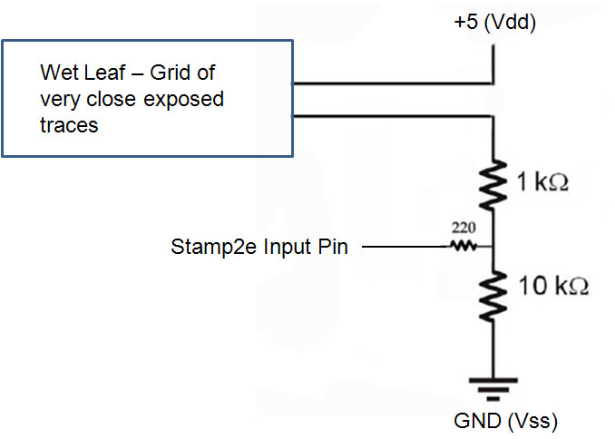
1) I have a simple configuration that wires a "wet leaf" sensor, which is a simple PCB with a two grids of exposed wire traces. The intent is to just measure the resistance between the two to determine if moisture is present.
2) I connect on set of traces on the wet leaf to Vdd (+5) and the other to ground through two 1k and 10k resistors wired in series.
3) I use a 220ohm resistor to connect in between the two resistors (1k and 10k) to an input pin on my Stamp 2e. I then make the pin an input, and see who wins out. . .the ground, or the +5v from the wet leaf.
The results are quite good, I can see the first drop of rain on the wet leaf.
PROBLEM: While I selected a gold plated we leaf, I'm seeing an alarming amount of corrosion on my sensor, after just a few weeks outdoors, and only 2 rainfalls. Is anyone aware of a better way to detect rain and avoid the corrosion issues I'm seeing here? Any novel ideas? Thanks!
-Jeff
678 x 484 - 51K
Comments
Mike, I can't afford three pins [noparse]:([/noparse]
Someone has suggested using a sensor grid with the traces much closer together, sealing them, and measuring them as a capacitor. . .apparently the rain changes the charge/discharge time. . .so I could use RCTIME, but I can't figure out how that could possibly work.
-Jeff
Post Edited (everest) : 10/21/2009 3:19:25 PM GMT
Leon
▔▔▔▔▔▔▔▔▔▔▔▔▔▔▔▔▔▔▔▔▔▔▔▔
Amateur radio callsign: G1HSM
Suzuki SV1000S motorcycle
http://www.emesys.com/OL2mhos.htm
http://www.emesystems.com/lwet_dat.htm
Also shown in the Applied Sensors Stamps-in-class. This circuit also works if the sensor is a capacitor instead of the resistor, but the traces do have to be very close together and insulated with something like soldermask, and the 555 run at a much higher frequency.
The rain impact idea that Leon brought up is used in the Vaisala WXT520 integrated weather module.
▔▔▔▔▔▔▔▔▔▔▔▔▔▔▔▔▔▔▔▔▔▔▔▔
Tracy Allen
www.emesystems.com
Leon, wouldn't I have to continuously monitor the film? One issue is that my application does a LOT of different things, so it only checks in with the environmental equipment every few seconds.
-Jeff
Leon
▔▔▔▔▔▔▔▔▔▔▔▔▔▔▔▔▔▔▔▔▔▔▔▔
Amateur radio callsign: G1HSM
Suzuki SV1000S motorcycle
Since they provide a frequency based representation of the amount of rain present, I can do some additional neat things, like distinguish between active rain and rain just sitting on the sensor. . .it should be pretty easy to see what's going on by watching the frequency stability and/or changes.
-Jeff
I just did an experiment, and here's what I've discovered. . .if I cover a wet leaf sensor with a single light coat of Krylon paint designed for outdoor use on plastics and metal. . .and swap out the resistors with MUCH higher values. . .I still get very reliable rain detection with just ridiculously low current flowing. I'm not sure how much a Stamp2 pin will sink when it's in INPUT mode, but we're talking about microamps of current here. . .
Is there any way to determine how quickly this sensor might be affected by electrolysis in this configuration? I've been googling and I can't figure out a way to calculate this.
-Jeff
Here is something else you might want to try that will exercise the polarity on the wet leaf ... not quite microcamps though about 1.5mA
The frequency will vary from about 4.2kHz to 15.4kHz depending on how saturated the wet leaf is.
▔▔▔▔▔▔▔▔▔▔▔▔▔▔▔▔▔▔▔▔▔▔▔▔
Beau Schwabe
IC Layout Engineer
Parallax, Inc.
I think I have most of these parts on hand, so I'll give this a try! Does reversing the polarity rapidly further reduce the corrosion due to electrolysis? I need to find myself a chemical engineer or something [noparse]:)[/noparse] This looks fundamentally similar to the LMC555 oscillator approach that the EME systems devices I've ordered use, but I love that I can build this one with parts on hand!!
-Jeff
-Jeff
There are electrochemical effects between dissimilar metals, even without external applied currents. Little batteries, with erosion of one of the metals at a rate roughly proportional to the electrode potential:
-- Gold against copper, -440 mV, copper erodes,
-- Tin against copper, 220 mV, tin erodes.
nickel is intermediate between gold and copper, very close to copper.
When a conductive grid is exposed outside, it collects dust and aerosols that increase the conductivity and response to high humidity and to light dew. Heavy rainfall will wash much of that off and reset the response to the clean level. It makes it hard to distinguish a light rain from high humidity, but if you are also measuring dew point, you can sort that out, but take care for the sky exposure, you know, cold sky. Crud on the sensor may exacerbate corrosion, particularly if the crud contains stuff like sulfur, as is common in agricultural settings.
Painting with flat latex paint is a usual practice for this type of sensor. It keeps surface contaminants away from direct contact with the bare metals and evens out the response. I add a small amount of gypsum to the paint in order to act as a chemical buffer, to counteract the effects of the external crud. I'm not sure what the effect of the paint is on the corrosion. It might slow it down by constraining the movement of ions, or not, an unresolved question.
A capacitance sensor to respond to the dielectric constant of water would be just like your existing grid, maybe with finer 8 mil traces. Add a 100% solder mask to insulate the traces. Even green to mimic a leaf. Paint it? The artificial leaf is then a capacitor of ~100pF, increasing dramatically when wet. Decagon makes a leaf wetness sensor based on the dielectric principle: www.decagon.com/canopy/leaf_wetness/
▔▔▔▔▔▔▔▔▔▔▔▔▔▔▔▔▔▔▔▔▔▔▔▔
Tracy Allen
www.emesystems.com
Post Edited (Tracy Allen) : 10/22/2009 7:18:56 PM GMT
I wonder if I couldn't create a capacitance sensor with the existing wet leaf sensors I have have. . .? Are there any restrictions on the type of pain I need to use that you can think of? I'm going to pick up some solder mask today. I want to try many different approached to this problem to make sure I have the best and most durable possible solution moving forward.
-Jeff
The capacitor method would be the best approach in terms of longevity. Designing a optimal circuit will depend of what the capacitance range is of the sensor itself.
▔▔▔▔▔▔▔▔▔▔▔▔▔▔▔▔▔▔▔▔▔▔▔▔
Beau Schwabe
IC Layout Engineer
Parallax, Inc.
-Jeff
I just took one of my grids, and coated it with a thin layer of GC silicone resin, and while still tacky laid on generic 0..5 mil polyethylene plastic wrap. Dry capacitance 50 pF, wet capacitance 200-500 pF. However, after a few minutes it quit and started reading 20kOhms DC resistance. Maybe there was a pinhole in the plastic. I guess the lesson is that the coating has to be good and stable.
Latex paint is permeable to water and cannot be used as insulation. On leaf wetness sensors it is used to spread out the response and to hold the water instead of allowing it to bead up. I think there would still be a place for flat exterior latex paint on top of the insulating layer, also to protect the soldermask from UV, and to isolate it from dust and other crud.
▔▔▔▔▔▔▔▔▔▔▔▔▔▔▔▔▔▔▔▔▔▔▔▔
Tracy Allen
www.emesystems.com
I'm going to leave this up on the roof running 24x7 for a few weeks and see what happens. Then I'll start trying some more elaborate solutions an boards. I've got 3 EME units on the way (Thanks Tracy!!) so I'm all set with those if necessary.
-Jeff
When I was a kid, I made a super high-tech rain sensor and it worked great.
I took a wooden clothes pin and wrapped some bare wire around the ends that normally touch together because of the spring pressure. I hooked the wires up to a buzzer, and then placed an aspirin between the contacts. When it rained, the aspirin would quickly dissolve, the contacts would close, and the buzzer would sound.
How's that for an elegant solution?
It actually worked very well. I tried to sell the idea to NASA for their recent bombing run on the moon (where they crashed a rocket into the moon and then sent a device through the dust that was kicked up in order to find moisture), but they foolishly declined. Have you ever read of a clothes pin failing in outer space? I thought not.
Brian