

PWM Transistor Heater
 Jeff R
Posts: 9
Jeff R
Posts: 9
Hello, I am trying to find information on using the BS2 and pwm to heat up a transistor. I can do the pwm part on the stamp, but I need to connect a transistor to act as the heater.
Similar to the electric heaters that go into shoes.
A transistor is used as the heating element and I am guessing that pwm is used to vary the temperature.
I have experimented with the example pwm projects for the BS2 lighting an LED and wanted to create something for heating shoes.
There are several of these electric heaters that exist, but I would like to build my own.
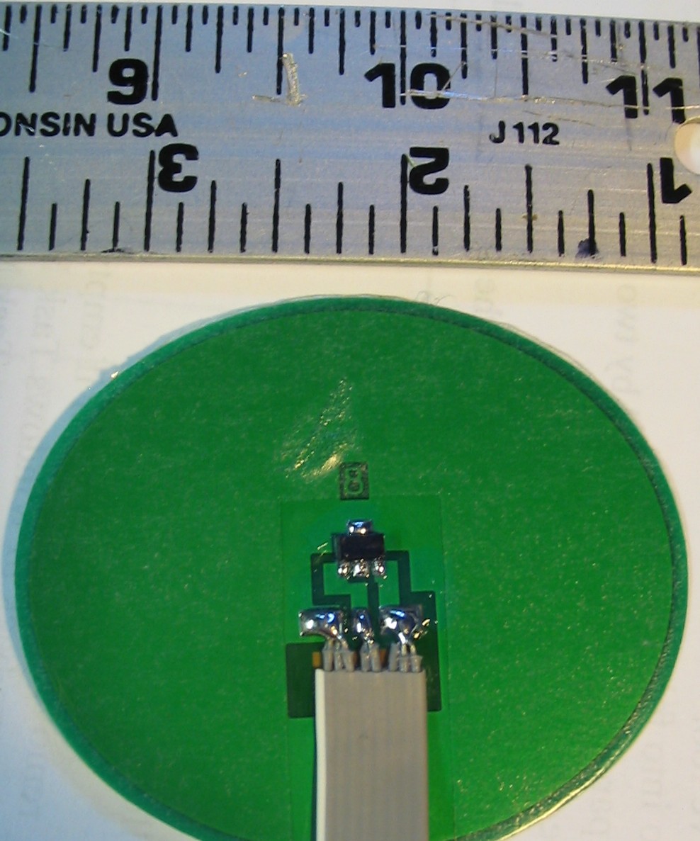
I actually bought a heating element pad that would go into shoes or ski boots. It has a SOT-223 4 pin transistor mounted to a thin copper coated pad or disc. I don't know if it is a MosFET, FET, NPN, PNP etc.
There is no other component such as a resistor on the transistor heating element.
I will be powering this with either 3.7v or 7.4v Li Ion batteries.
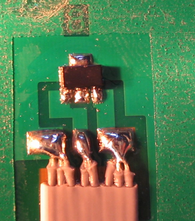
The label on the transistor in the pictures looks like it is "cb sa s82". It is coated, so it is hard to see exactly.
Thank you if anyone has some info, Jeff
Post Edited (Jeff R) : 10/18/2009 6:39:37 PM GMT
Similar to the electric heaters that go into shoes.
A transistor is used as the heating element and I am guessing that pwm is used to vary the temperature.
I have experimented with the example pwm projects for the BS2 lighting an LED and wanted to create something for heating shoes.
There are several of these electric heaters that exist, but I would like to build my own.
I actually bought a heating element pad that would go into shoes or ski boots. It has a SOT-223 4 pin transistor mounted to a thin copper coated pad or disc. I don't know if it is a MosFET, FET, NPN, PNP etc.
There is no other component such as a resistor on the transistor heating element.
I will be powering this with either 3.7v or 7.4v Li Ion batteries.
The label on the transistor in the pictures looks like it is "cb sa s82". It is coated, so it is hard to see exactly.
Thank you if anyone has some info, Jeff
Post Edited (Jeff R) : 10/18/2009 6:39:37 PM GMT
988 x 1187 - 214K
651 x 737 - 131K
Comments
Hard to tell from your pics, but I'd say the copper plate is a heat sink for the transistor and the multiple wires are the actual heating element.
Cheers,
▔▔▔▔▔▔▔▔▔▔▔▔▔▔▔▔▔▔▔▔▔▔▔▔
Tom Sisk
http://www.siskconsult.com
·
The heater is only the transistor with the copper coated disk acting as a heat spreader.
Thanks for your reply Tom,
Jeff
I had a look at the SOT-223 data and came across a Motorola doc describing how to increase the power handling capability of the device:
"The most cost effective approach of designing layout 2 (0.066 square inches copper pad
directly under the package), without occupying additional board space, can increase the maximum
power from approximately 1.1 to 1.3W."
Having asked my feet to spend 55+ plus winters in ice and snow, I can't believe 1.3 watts will do much to warm your tootsies!
Cheers,
▔▔▔▔▔▔▔▔▔▔▔▔▔▔▔▔▔▔▔▔▔▔▔▔
Tom Sisk
http://www.siskconsult.com
·