Shop OBEX P1 Docs P2 Docs Learn Events
PhotoTransistor Question — Parallax Forums

PhotoTransistor Question

anita1984anita1984 Posts: 23
edited 2009-10-12 23:04 in Accessories
Hi forum ,
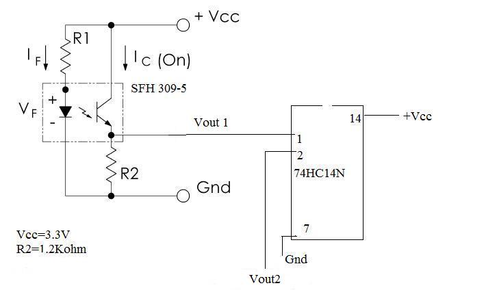
I would like to ask you·about the circuit in the attachment , I am using a phototransistor SFH 309-5 and a 74HC14N to measure the speed of a motor·, i measure on Vout2 their is no voltage·, what do you recommend me ? is this a problem of the choise of R2?
Have a nice day,
Anita
726 x 424 - 21K
1.jpg 21.1K

Comments

  • Mike GreenMike Green Posts: 23,101
    edited 2009-10-11 21:20
    What is the value of R1? What voltage do you measure at Vout1? You should measure 0V when the LED is off and +3.3V when the LED is on.
  • PJAllenPJAllen Banned Posts: 5,065
    edited 2009-10-11 21:59
    The output of the opto should be Common Emitter.

    ·attachment.php?attachmentid=64345
    599 x 358 - 23K
  • Phil Pilgrim (PhiPi)Phil Pilgrim (PhiPi) Posts: 23,514
    edited 2009-10-11 23:03
    Common emitter vs. common collector: it doesn't matter; either circuit will work. One will give a logic low with received light; the other, a logic high. All that matters is that between light and dark, there's a transition that spans the logic threshold of the device the output is connected to. This will depend on the values of the two resistors and on the efficiency of the optical coupling.

    -Phil
  • PJAllenPJAllen Banned Posts: 5,065
    edited 2009-10-11 23:39
    Isn't the CC more susceptible to the optical coupling, CMRR, CTR, etc.?· With the CE I figure with a modest forward-bias on the IRED and some non-critical output pull-up (470Ω to 10K and more) you're in sat-switch heaven, good-to-go.

    Post Edited (PJ Allen) : 10/12/2009 12:16:44 AM GMT
  • Phil Pilgrim (PhiPi)Phil Pilgrim (PhiPi) Posts: 23,514
    edited 2009-10-11 23:53
    PJ Allen said...
    Isn't the CC more susceptible to the optical coupling, CMRR, etc.?
    No. The LED and optotransistor don't have to share a ground reference (which is the basis for optoisolation), so the phototransistor doesn't "know" which terminal is connected to a resistor and which to a supply. The only behavior that matters is that the current through it increases with the amount of light it receives. And this current can be used either to source a load or to sink one — with equal facility.

    -Phil
  • PJAllenPJAllen Banned Posts: 5,065
    edited 2009-10-12 00:14
    I wrote CMRR, when I should have wrote CTR.

    WEll, anyway, the last thing I want is for this thread to go side-ways with a dozen Replies about thus and sundry and nothing from the OP.

    Good luck.
  • kwinnkwinn Posts: 8,697
    edited 2009-10-12 02:20
    This circuit will not produce a voltage out that is proportional to the speed of the motor if that is what you are looking for. It will produce pulses out with a frequency proportional to the speed as long as R1 and R2 are of appropriate values. It will work with R2 connected to the emitter or the base of the transistor with proper values for R1 and R2.
  • ElectricAyeElectricAye Posts: 4,561
    edited 2009-10-12 02:39
    Anita,

    are you trying to convert a pulse frequency (generated by a photo-interruptor) into a DC voltage?
  • anita1984anita1984 Posts: 23
    edited 2009-10-12 05:40
    Hello,
    thank you all , almost all of you speaking about appropriate value of R1 and R2 , what they should be the value if i have the emitter is 3V, 45mA.
    thank you in advance
  • Phil Pilgrim (PhiPi)Phil Pilgrim (PhiPi) Posts: 23,514
    edited 2009-10-12 05:53
    Anita,

    Your 3V emitter voltage sounds as if you're using a white LED. Is there any particualr reason for this? The detector sensitivity peaks in the red to near IR, so a red LED would work just as well.

    The reason I bring this up is that with a 3.3V supply, a 3V LED doesn't leave you with much headroom for a current-limiting resistor. So it's hard to recommend a value for R1 under these conditions, since the forward voltages within a batch of LEDs can vary so much. A red LED with, typically, a much lower forward voltage would be easier to regulate.

    As to the value of R2, it will have to be determined by experimentation. So much depends on how much light reaches the sensor during the "on" and "off" conditions. Can you tell us a little more about your physical setup? For example, are you looking through a slotted disk or at reflected light?

    -Phil
  • anita1984anita1984 Posts: 23
    edited 2009-10-12 05:58
    it's a red laser diode module. looking through a reflected light.
    Thanks
  • kwinnkwinn Posts: 8,697
    edited 2009-10-12 15:14
    Anita1984, first in my earlier post I stated "It will work with R2 connected to the emitter or the base". That should have been "emitter or collector". Sorry for the mistake.

    To get 45mA through the laser diode with a 3.3V source and a diode forward voltage of 3V you would need a resistor value of (3.3 - 3.0) / 0.045 = 6.666 ohms. The closest standard resistor value would be 6.8 ohms for a current of 44.1mA. If you need to get closer to 45mA you could put a 330 ohm resistor in parallel with the 6.8 ohm one.
  • C-BobC-Bob Posts: 19
    edited 2009-10-12 21:42
    Your photo transistor have clear or blue material? Blue have filter for 880nm (750 - 1100nm for 10% sensitivity) useable is clear (red laser have 680)

    ▔▔▔▔▔▔▔▔▔▔▔▔▔▔▔▔▔▔▔▔▔▔▔▔
    C-Bob

    Every problem·have at least one·nice, simply and·wrong solution.
  • Phil Pilgrim (PhiPi)Phil Pilgrim (PhiPi) Posts: 23,514
    edited 2009-10-12 23:04
    I takes more than a series resistor to regulate a laser diode. If you do so, you risk thermal runaway, which will destroy the diode. Google "laser diode" regulator -patent -ieee for some suggested circuits.

    -Phil
Sign In or Register to comment.