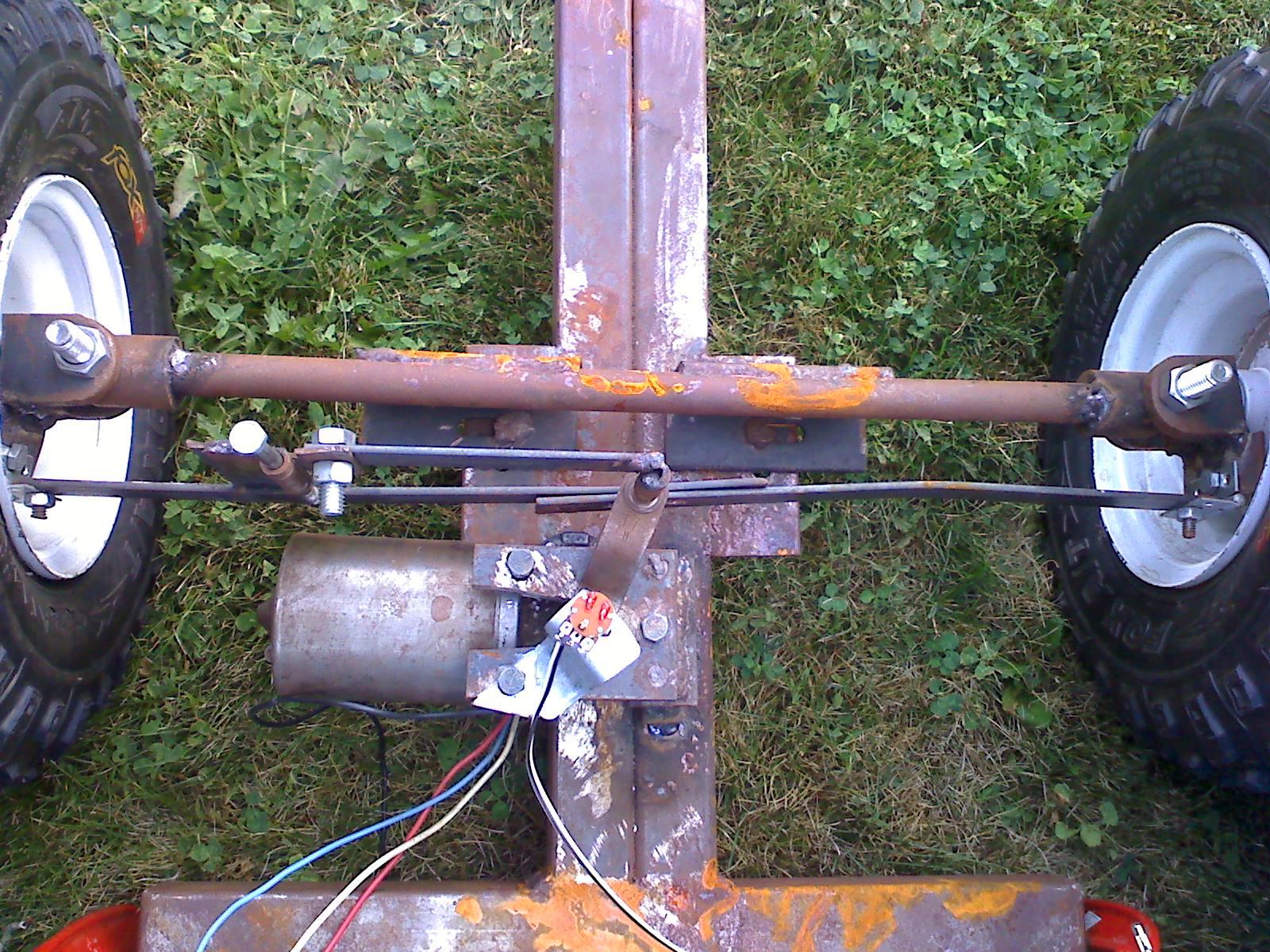
Suggestions for increasing the torque on robot steering system--new system almo
Hey guys, I can't go to school this week so I figured I would start working harder to get my bot up and running. Only prob, the steering motor runs too fast so it doesn't have the torque needed to turn the wheels. If any of you have had to do with something similar please explain what you did, it would help me immensely. Check out the photos if you are curious on my current setup. Suggestions/comments are welcome.
▔▔▔▔▔▔▔▔▔▔▔▔▔▔▔▔▔▔▔▔▔▔▔▔
PG
Post Edited (Pi Guy) : 11/8/2009 10:56:49 PM GMT
▔▔▔▔▔▔▔▔▔▔▔▔▔▔▔▔▔▔▔▔▔▔▔▔
PG
Post Edited (Pi Guy) : 11/8/2009 10:56:49 PM GMT


Comments
Duffer
The choices I can see are
different motor - slower/more torque - maybe a window motor since they often have the 90degree turn built in and tend to have a lot of torque
Add gearing between motor and turning arm
Change gearing and arm to be a screw gear - attach a screw rod to the motor, attach the nut to the steering column, when the motor turns it turns the screw rod then the nut can move side to side, this gives a large increase in torque.
▔▔▔▔▔▔▔▔▔▔▔▔▔▔▔▔▔▔▔▔▔▔▔▔
Beau Schwabe
IC Layout Engineer
Parallax, Inc.
Last week there was a boat in the school welding shop that some people were working on with a steering system where when the steering wheel was turned a piston-type end to a flexible tube would push in/out. If I could figure out how to make something like that to put on my motor all I would have to do is make a mount for the piston to push on the steering bar. The only problem is once I get it done it might be more complex than the ideas you guys already mentioned.
▔▔▔▔▔▔▔▔▔▔▔▔▔▔▔▔▔▔▔▔▔▔▔▔
PG
▔▔▔▔▔▔▔▔▔▔▔▔▔▔▔▔▔▔▔▔▔▔▔▔
PG
Check this thread out for an actuator that I built for steering...
http://forums.parallax.com/showthread.php?p=525233
▔▔▔▔▔▔▔▔▔▔▔▔▔▔▔▔▔▔▔▔▔▔▔▔
Beau Schwabe
IC Layout Engineer
Parallax, Inc.
▔▔▔▔▔▔▔▔▔▔▔▔▔▔▔▔▔▔▔▔▔▔▔▔
PG
▔▔▔▔▔▔▔▔▔▔▔▔▔▔▔▔▔▔▔▔▔▔▔▔
PG
Just wondering...why am I posting this info anyway?
Many people report they are having a problem and then disappear into the ether. It is really encouraging to see someone work through a problem, you know they will really build robots. Congratulations.
▔▔▔▔▔▔▔▔▔▔▔▔▔▔▔▔▔▔▔▔▔▔▔▔
My Robots
Rich H
▔▔▔▔▔▔▔▔▔▔▔▔▔▔▔▔▔▔▔▔▔▔▔▔
The Simple Servo Tester, a kit from Gadget Gangster.
▔▔▔▔▔▔▔▔▔▔▔▔▔▔▔▔▔▔▔▔▔▔▔▔
PG
▔▔▔▔▔▔▔▔▔▔▔▔▔▔▔▔▔▔▔▔▔▔▔▔
PG
Good intro to Ackerman steering at http://www.rctek.com/technical/handling/ackerman_steering_principle.html
Your lead screw is very nice part, probably with ground or rolled threads. It has a very course angle, and was probably designed for a recirculating ball bearing application, like a cars' steering box. Looks like you made a threaded nut-like part from a square steel channel. No mean feat! But since you're rubbing instead of rolling, there will be lots of friction. You will want to use lots of serious lithium or silicone grease on those threads, and cover the whole assembly with something like a CV joint boot or flexible bellows on each side to keep dirt out and grease in.
A few more suggestions: make your pivoted connection to your square nut·in line with·the leadscrew. Anywhere else will cause the nut to cock and bind on the leadscrew. Also lubricate every pivot in your steering linkage, there will be a lot of wear & tear. Good luck, and keep posting your updates!
▔▔▔▔▔▔▔▔▔▔▔▔▔▔▔▔▔▔▔▔▔▔▔▔
·"If you build it, they will come."
Post Edited (erco) : 10/30/2009 7:30:46 PM GMT
Just to explain things further--I'm not sure what you are talking about with the lead screw, but if you're talking about the part that the 1X2" tubing is on it is actually a drill bit for cutting cement. It was just lying around, so I used it. I used tig to weld it to stainless pipe so it would fit in the 1" bearing, unfortunately making it lopsided, and then I pressed it in tightly so it isn't even necessary to use the set screws on the bearing. The part holding the bearing is just a pipe I cut and beveled to make it fit, and welded the other pieces to it so it would hold it and be easily mounted. The 1x2" metal part I mentioned earlier is just that, but with a 1/2" hole drilled in one side and a 3/4" hole in the other. To get it to fit in the 1/2" side, I used a grinder cutting blade to put a slot in it, forcing it to move with the screw, or drill bit. Hope this answered any questions, it really isn't too complex.
▔▔▔▔▔▔▔▔▔▔▔▔▔▔▔▔▔▔▔▔▔▔▔▔
PG
▔▔▔▔▔▔▔▔▔▔▔▔▔▔▔▔▔▔▔▔▔▔▔▔
PG
▔▔▔▔▔▔▔▔▔▔▔▔▔▔▔▔▔▔▔▔▔▔▔▔
PG
▔▔▔▔▔▔▔▔▔▔▔▔▔▔▔▔▔▔▔▔▔▔▔▔
PG
▔▔▔▔▔▔▔▔▔▔▔▔▔▔▔▔▔▔▔▔▔▔▔▔
PG
·
▔▔▔▔▔▔▔▔▔▔▔▔▔▔▔▔▔▔▔▔▔▔▔▔
PG
It isn't done but it's functional. I still need to give it wider turning angles and give it more torque by increasing the leverage on the steering bar. Then I intend to use a ping to inform me of the turning angle since it is easiest. After everything is where I want it I will attach the steel cable to it instead of that wire and make it permanent on the fully functional and finally finished steering system. Next up: brakes
▔▔▔▔▔▔▔▔▔▔▔▔▔▔▔▔▔▔▔▔▔▔▔▔
PG