LED Temp. Project.
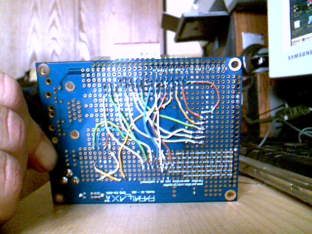
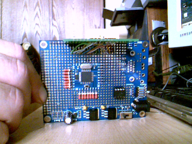
For months I have been working on two projects. 1. the HC4LED temp project. and 2. Ken Gracy's temp project. Well I have both of them working (some what) but with all my projects they need debugging. Now some of the people in the forum can see what Ken's project might look from the bottom (sorry Ken) At least I know now they can be done. All objects for these two projects can be found in both the forum (do a search for HC4LED) and in Obex at the Parallax web site. I'm glad I won a Demo Board at the Wooster Library Prop meeting ( Thank You OBC.) and Thanks to Parallax.
Post Edited (TheWizard65) : 9/28/2009 8:09:26 PM GMT
Post Edited (TheWizard65) : 9/28/2009 8:09:26 PM GMT


Comments
Now that you've got it working, how about doing the same thing with a TV or VGA display? It'll be child's play compared to what you've just experienced. Looks like you need the VGA connector for the Prop Proto Board and then you'll be ready!
Sincerely,
Ken Gracey
Ken I do have the set up for VGA, it was part of the door prize at the last expo. So again my hats off to Parallax and OBC and his crew. Oh BTW, this was done without a diagram or schematic, only a picture of Ken"s Project.
I am in fact having trouble displaying a seven, any help would be greatly appreciated.
Post Edited (TheWizard65) : 9/27/2009 11:49:27 PM GMT
Good luck on all future projects!
▔▔▔▔▔▔▔▔▔▔▔▔▔▔▔▔▔▔▔▔▔▔▔▔
Quit buying all those fixed voltage regulators, and·get an Adjustable Power Supply·for your projects!· Includes an LED testing terminal!
*-NEW-* SD Card Adapter·Now available!· Add extra memory to your next Propeller project with ease!
Awesome! I'm betting you've learned some spin while doing this!
Congrats on getting into the software side of things as well as the hardware.
Looks like you took the hard way and wired your own LED digits instead of
using that ready-made solution. AWESOME!
Here's your next challenge...
You could save I/O lines by connecting each of the same LED segments to
a single I/O line, then connect the GND of each LED digit to another I/O pin.
By quickly triggering the GND lines you could jump quickly from digit to
digit, lighting the segment you need at that moment.
(If you do it fast enough, your eyes won't be able to tell and both digits
will appear to be displaying data, just a little dimmer than before.)
Don't rip apart your current project to do this! Let me know if you need
another protoboard. (I KNOW you have plenty of LED digits on hand. [noparse]:)[/noparse]
OBC
▔▔▔▔▔▔▔▔▔▔▔▔▔▔▔▔▔▔▔▔▔▔▔▔
New to the Propeller?
Visit the: The Propeller Pages @ Warranty Void.
Post Edited (Oldbitcollector) : 9/28/2009 2:45:17 AM GMT
▔▔▔▔▔▔▔▔▔▔▔▔▔▔▔▔▔▔▔▔▔▔▔▔
Propeller Wiki: Share the coolness!
Chat in real time with other Propellerheads on IRC #propeller @ freenode.net
Safety Tip: Life is as good as YOU think it is!
▔▔▔▔▔▔▔▔▔▔▔▔▔▔▔▔▔▔▔▔▔▔▔▔
Chris Savage
Parallax Engineering
50 72 6F 6A 65 63 74 20 53 69 74 65
·
Ooops Sorry Chris I'll change it. I'll get to work uploading the sorce Code, and Schematic asap!
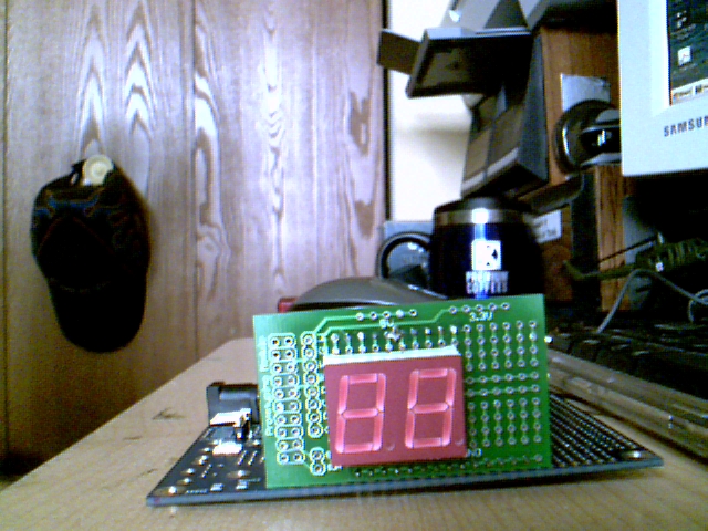
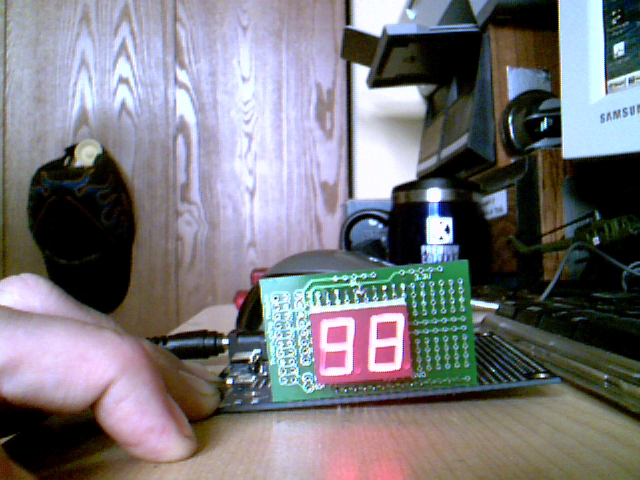
My Project takes a reading from the DS1620 Digital Temperature Sensor and Display's it on a 2 Digit 7 Segment LED Display. Using Spin code created by Ken Gracey. Who infact created the first Project of this type.
Here is the source code, It will take me some time to do the schematic, how ever there are pictures above in the first line of this thread. Sorry for not checking the guidelines. I was excited.
I must add I am having some problem displaying a 7 in the tens column (7?)
Post Edited (TheWizard65) : 9/28/2009 8:41:05 PM GMT
▔▔▔▔▔▔▔▔▔▔▔▔▔▔▔▔▔▔▔▔▔▔▔▔
Chris Savage
Parallax Engineering
50 72 6F 6A 65 63 74 20 53 69 74 65
·
I would have drawn lines representing the wired connection but it would make it a big mess.
You'll get slightly better *F accuracy if you take the decimal portion of the reading that the DS1620 object returns and make a rounding choice based on it. I noticed that doing this caused my thermostat to track better since it no longer displays 78.8 (788) as 78. It moves it up to 79.
I divide by ten to get the whole part 788/10 = 78 (integer div)
I modulus by ten to get the decimal 788//10 = 8
I compare the decimal to 5 and if it's equal or greater then I add one to the whole part.
I like your clear case.
Just one question - where is the DS1620 hooked up? I did not see it.
The DS1620's Pin out is as follow's: DQ = Pin 16 , CLK = Pin 17 , RST = 18 , GND = VSS , VDD = 5v
Sorry about not having this proper Posted.
Post Edited (TheWizard65) : 11/27/2009 4:37:19 PM GMT