

Simulator
 Husker
Posts: 15
Husker
Posts: 15
I am trying to build simulator for a pressure decoder at work. The decoder monitors a pressure signal. A device at distance from the sensor creates pressures spikes in a Morse code type of format. The decoder recognizes these spikes in a timed sequence and provides readable data.
The pressure sensor is a transducer that creates variances in resistance. Right not I am using the AD5220 to try to replicate the signal. So far I have been able to create the signal but with flaws. When I use software to perform a FFT it comes out completely erratic. I have tried several options. Adding capacitors to the circuit and adjustments in programming have helped smooth out the signal so at least it isn't a square wave.
Is there something I can add to the circuit or anything in particular I should look at in the programming? Any help is appreciated.
Note:
-Decoder reads current from 4-20mA
-Decoder reads changes in pressure, not the magnitude (it flat lines at the same point whenever the pressure signal settles)
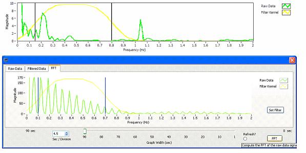
*The top FFT below is the real signal and the bottom FFT is the simulated signal
D = T/21
Z = 0
DEBUG "Total Time=", DEC(T),CR
DEBUG "Data Slot=", DEC(D),CR
DEBUG "Pulse Time=", DEC(P),CR,CR
Main:
'Drop to lowest possible resistance
HIGH 0
HIGH 1
LOW 14
LOW 15
FOR x = 1 TO 100 'Approximate drop of 150*80=12000ohms (Max is 10K)
LOW 1
HIGH 1
NEXT
'Survey Routine
DO
PAUSE 10000 'Allows SIU to stabilize
GOSUB Sync
'FID Pulses
GOSUB DATA0
GOSUB DATA0
'MFCX Pulses
GOSUB Data0
GOSUB DATA0
'AZUX Pulses
GOSUB DATA0
GOSUB Data0
GOSUB DATA0
'INCX Pulses
GOSUB DATA0
GOSUB DATA0
GOSUB DATA0
'MDAX Pulses
GOSUB DATA0
GOSUB DATA0
'BSPX Pulse
GOSUB DATA0
'PBVX Pulses
GOSUB DATA0
LOOP
Sync:
FOR x = 1 TO 4
GOSUB Pulse
PAUSE (24*D-(4*P))/4
NEXT
RETURN
Data0:
PAUSE 0
GOSUB pulse
PAUSE T-P
RETURN
DATA1:
PAUSE D
GOSUB pulse
PAUSE T-D-P
RETURN
DATA2:
PAUSE D*2
GOSUB pulse
PAUSE T-D*2-P
RETURN
DATA3:
PAUSE D*3
GOSUB pulse
PAUSE T-D*3-P
RETURN
DATA4:
PAUSE D*4
GOSUB pulse
PAUSE T-D*4-P
RETURN
DATA5:
PAUSE D*5
GOSUB pulse
PAUSE T-D*5-P
RETURN
DATA6:
PAUSE D*6
GOSUB pulse
PAUSE T-D*6-P
RETURN
DATA7:
PAUSE D*7
GOSUB pulse
PAUSE T-D*7-P
RETURN
DATA8:
PAUSE D*8
GOSUB pulse
PAUSE T-D*8-P
RETURN
DATA9:
PAUSE D*9
GOSUB pulse
PAUSE T-D*9-P
RETURN
DATA10:
PAUSE D*10
GOSUB pulse
PAUSE T-D*10-P
RETURN
DATA11:
PAUSE D*11
GOSUB pulse
PAUSE T-D*11-P
RETURN
DATA12:
PAUSE D*12
GOSUB pulse
PAUSE T-D*12-P
RETURN
DATA13:
PAUSE D*13
GOSUB pulse
PAUSE T-D*13-P
RETURN
DATA14:
PAUSE D*14
GOSUB pulse
PAUSE T-D*14-P
RETURN
DATA15:
PAUSE D*15
GOSUB pulse
PAUSE T-D*15-P
RETURN
Pulse:
Z = Z + 1
DEBUG "Pulse", DEC(Z),CR
LOW 0
LOW 1
HIGH 15
PAUSE P/2
HIGH 1
HIGH 0
LOW 1
LOW 15
PAUSE P/2
HIGH 1
RETURN
The pressure sensor is a transducer that creates variances in resistance. Right not I am using the AD5220 to try to replicate the signal. So far I have been able to create the signal but with flaws. When I use software to perform a FFT it comes out completely erratic. I have tried several options. Adding capacitors to the circuit and adjustments in programming have helped smooth out the signal so at least it isn't a square wave.
Is there something I can add to the circuit or anything in particular I should look at in the programming? Any help is appreciated.
Note:
-Decoder reads current from 4-20mA
-Decoder reads changes in pressure, not the magnitude (it flat lines at the same point whenever the pressure signal settles)
*The top FFT below is the real signal and the bottom FFT is the simulated signal
D = T/21
Z = 0
DEBUG "Total Time=", DEC(T),CR
DEBUG "Data Slot=", DEC(D),CR
DEBUG "Pulse Time=", DEC(P),CR,CR
Main:
'Drop to lowest possible resistance
HIGH 0
HIGH 1
LOW 14
LOW 15
FOR x = 1 TO 100 'Approximate drop of 150*80=12000ohms (Max is 10K)
LOW 1
HIGH 1
NEXT
'Survey Routine
DO
PAUSE 10000 'Allows SIU to stabilize
GOSUB Sync
'FID Pulses
GOSUB DATA0
GOSUB DATA0
'MFCX Pulses
GOSUB Data0
GOSUB DATA0
'AZUX Pulses
GOSUB DATA0
GOSUB Data0
GOSUB DATA0
'INCX Pulses
GOSUB DATA0
GOSUB DATA0
GOSUB DATA0
'MDAX Pulses
GOSUB DATA0
GOSUB DATA0
'BSPX Pulse
GOSUB DATA0
'PBVX Pulses
GOSUB DATA0
LOOP
Sync:
FOR x = 1 TO 4
GOSUB Pulse
PAUSE (24*D-(4*P))/4
NEXT
RETURN
Data0:
PAUSE 0
GOSUB pulse
PAUSE T-P
RETURN
DATA1:
PAUSE D
GOSUB pulse
PAUSE T-D-P
RETURN
DATA2:
PAUSE D*2
GOSUB pulse
PAUSE T-D*2-P
RETURN
DATA3:
PAUSE D*3
GOSUB pulse
PAUSE T-D*3-P
RETURN
DATA4:
PAUSE D*4
GOSUB pulse
PAUSE T-D*4-P
RETURN
DATA5:
PAUSE D*5
GOSUB pulse
PAUSE T-D*5-P
RETURN
DATA6:
PAUSE D*6
GOSUB pulse
PAUSE T-D*6-P
RETURN
DATA7:
PAUSE D*7
GOSUB pulse
PAUSE T-D*7-P
RETURN
DATA8:
PAUSE D*8
GOSUB pulse
PAUSE T-D*8-P
RETURN
DATA9:
PAUSE D*9
GOSUB pulse
PAUSE T-D*9-P
RETURN
DATA10:
PAUSE D*10
GOSUB pulse
PAUSE T-D*10-P
RETURN
DATA11:
PAUSE D*11
GOSUB pulse
PAUSE T-D*11-P
RETURN
DATA12:
PAUSE D*12
GOSUB pulse
PAUSE T-D*12-P
RETURN
DATA13:
PAUSE D*13
GOSUB pulse
PAUSE T-D*13-P
RETURN
DATA14:
PAUSE D*14
GOSUB pulse
PAUSE T-D*14-P
RETURN
DATA15:
PAUSE D*15
GOSUB pulse
PAUSE T-D*15-P
RETURN
Pulse:
Z = Z + 1
DEBUG "Pulse", DEC(Z),CR
LOW 0
LOW 1
HIGH 15
PAUSE P/2
HIGH 1
HIGH 0
LOW 1
LOW 15
PAUSE P/2
HIGH 1
RETURN
597 x 300 - 30K
Comments
▔▔▔▔▔▔▔▔▔▔▔▔▔▔▔▔▔▔▔▔▔▔▔▔
Tom Sisk
http://www.siskconsult.com
·
Your transducer produces an anaolg signal proportional to pressure applied. That 4 - 20 mA is measured in some instrument, controller or logger.
The AD5220 is nothing more than a potentiometer whose wiper position is controlled by sending the chip pulses and an up/down direction command.
I can't tell from your chip schematic exactly what you're doing as it looks like you've got the pot in series with the 100K. What is the "I" representing? For sure you are not simulating a 4 - 20 mA signal.
Assuming the instrument you're trying to drive is really looking for a voltage of 1 to 5 volts, the pot chip may work if you reconnect it as a potentiometer ( a to +, b to 0v, w as wiper). Then your simulated waveform will be limited by the fact that you only have 128 possible steps and the transitions will affect your FFT.
You might be better off to use a 12-bit d/a which would give you 4096 steps. Then, if you're instrument really wants 4 - 20 mA, just feed your 1 - 5 v d/a signal into a commercial signal converter to give you a real 4 - 20 mA signal.
Cheers
▔▔▔▔▔▔▔▔▔▔▔▔▔▔▔▔▔▔▔▔▔▔▔▔
Tom Sisk
http://www.siskconsult.com
·