Low cost wireless LCD display
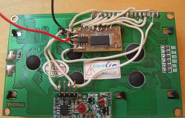
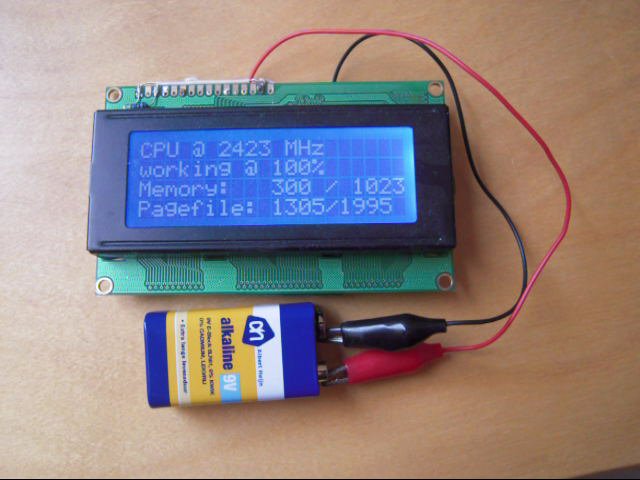
Using easy to get and cheap components, Vinnie (another forum user) and I have created a 433Mhz wireless 4x20 LCD display. Basically, I've put together lots of code I could grab from open sources, such as parallax reference code and fragments from sxlist.com. Vinnie was kind enough to create a PCB design to fit all 'vanilla' SX components (resonator, voltage regulator, etc) on a small print, allowing all components to be 'hidden' behind the LCD print in a very small space.

(I know, I know, my soldering skills are typical for a software engineer)

This short youtube video gives an idea of how it can be used.
The attached code contains:
- an adaptation of a well-known implementation of an RS-232 VP
- an adaptation of the original 4 line LCD display reference code as available on the parallax website
- some CRC16 checksum code found on sxlist.com
- my own implementation of an arbitrary size round-robin buffer that resides in the last n bytes of ram
- my own implementation of a communications protocol that uses packets of at most 16 bytes data, 8 bit addressing and 16 bit error detection.
I've also created a driver for a popular Windows LCD program called 'LCD Smartie', allowing the homebrew wireless LCD to be used with standard modules that show CPU usage, mail status, etc. Since this code has it's own installation requirements, I'm going to dedicate a separate post on this thread to that.
Basic working of the SX code is as follows:
port ra.0 acts as a regular 2400bps 8n1 serial port input. This pin will normally be directly connected to the output of a 433Mhz receiver. Our experience is that 433Mhz receivers are very noisy if nobody is transmitting. The receiver will give of random bits, which would mean that the display would show lots of garbage if we were to just put the received bytes on the LCD display directly.
To prevent that, and to allow for some kind of addressing, a simple packet-based protocol was created on top of the rs-232 protocol. The protocol sends packets of at most 16 bytes of data at a time in the following format:
The main (non-interrupt-) code then picks up the bytes from the round-robin buffer and will basically send the received characters directly to the LCD display. A small set of special command characters is implemented to allow clearing the display (CLS) and to position the cursor. This command set could be easily extended.
I'm using all of this myself currently to have an LCD display in the living room that tells me whether I have new email and to display some interesting logs from a web-server. I intend to allow multiple senders to send information to the display, so that I could see caller-id information when somebody calls, browse through the menu structure of my media pc while the TV is switched off (for playing music, obviously), etc.
I don't have an informative schematic, but I think the pin assignments in the SX code speak for themselves, this is really not a very complex hardware setup:
Post Edited (spiff) : 8/31/2009 1:05:41 AM GMT
(I know, I know, my soldering skills are typical for a software engineer)
This short youtube video gives an idea of how it can be used.
The attached code contains:
- an adaptation of a well-known implementation of an RS-232 VP
- an adaptation of the original 4 line LCD display reference code as available on the parallax website
- some CRC16 checksum code found on sxlist.com
- my own implementation of an arbitrary size round-robin buffer that resides in the last n bytes of ram
- my own implementation of a communications protocol that uses packets of at most 16 bytes data, 8 bit addressing and 16 bit error detection.
I've also created a driver for a popular Windows LCD program called 'LCD Smartie', allowing the homebrew wireless LCD to be used with standard modules that show CPU usage, mail status, etc. Since this code has it's own installation requirements, I'm going to dedicate a separate post on this thread to that.
Basic working of the SX code is as follows:
port ra.0 acts as a regular 2400bps 8n1 serial port input. This pin will normally be directly connected to the output of a 433Mhz receiver. Our experience is that 433Mhz receivers are very noisy if nobody is transmitting. The receiver will give of random bits, which would mean that the display would show lots of garbage if we were to just put the received bytes on the LCD display directly.
To prevent that, and to allow for some kind of addressing, a simple packet-based protocol was created on top of the rs-232 protocol. The protocol sends packets of at most 16 bytes of data at a time in the following format:
- <preamble, a string of zero-valued bytes, at least one byte long>
- 55H (start of packet)
- address byte (0-255, packet will be ignored if the address does not match the device address)
- packet size byte (0-15, upper nibble is ignored and reserved for future use. 0 means 1 data byte, 15 means 16 data bytes)
- n bytes of payload data
- 2 bytes of checksum, packet will be discarded if checksum is incorrect.
The main (non-interrupt-) code then picks up the bytes from the round-robin buffer and will basically send the received characters directly to the LCD display. A small set of special command characters is implemented to allow clearing the display (CLS) and to position the cursor. This command set could be easily extended.
I'm using all of this myself currently to have an LCD display in the living room that tells me whether I have new email and to display some interesting logs from a web-server. I intend to allow multiple senders to send information to the display, so that I could see caller-id information when somebody calls, browse through the menu structure of my media pc while the TV is switched off (for playing music, obviously), etc.
I don't have an informative schematic, but I think the pin assignments in the SX code speak for themselves, this is really not a very complex hardware setup:
SerialIn    =    ra.0
led        =     rb.7
lcd_control    =    ra
lcd_RS        =    ra.1        ; 0 = i--nstruction, 1 = data
lcd_RW        =    ra.2        ; 0 = write, 1 = read
lcd_E        =    ra.3        ; 1,1-->0 is the LCD enable
lcd_DB4        =    rb.0        ; DB4 = Data bus line 4 (LSB)
lcd_DB5        =    rb.1
lcd_DB6        =    rb.2
lcd_DB7        =    rb.3        ; DB7 = Data bus line 7 (MSB)
Post Edited (spiff) : 8/31/2009 1:05:41 AM GMT


Comments
For programming the SX I've used contact points to avoid a·header (which would make the print substantially larger). Using a pin header in the SX Key and pressing it down programming is possible.
Components:
SX28 SOIC
4Mhz SMD resonator
10k R
100nF SMD
xxL05 voltage regulator (8 pin DIL SMD type)
The voltage regulator is optional, but the board design uses the internal connection of the DIL regulator (between pins 2,3,6 and 7) as a wire bridge, so if it is left out, you'll need to put that in manually. R2 is also optional, it can hold the·resistor for the display backlight. Or a power led i.e.
The 'solder bridges'·at the top of the print are intended·for coding the receiver. This way you can (theoretically) use 256 multiple modules together without interference.
On the backside of the Display print you can see the receiver module attached to the display. The solder joints might suggest·I'm not nearly as good a coder as Spiff.. which is very much true (though I also did a very little·coding in the src to rectify the line order)
For the prototyping I've added a temporary header for easier programming and 9V·cap because I didn't have the AAA holders yet. I've attached the receiver module at the side, which seemed a more suitable place for optimal reception (less interference of the CPUs).
The latter might be true, but·unfortunately the alu Casing (which is an Ipod protector case I think) blocks the onboard antenna of the receiver module. So either I'd have to replace it with a plastic casing, or I need to get·a receiver module with external antenna.
Post Edited (Vinnie) : 8/31/2009 7:32:15 PM GMT
Cool project
Could you post the files that you used to make this board
433Mhz receiver and· 433 Mhz transmitter
Who make the receiver and transmitter and what is the range in feet that you can have them apart and still work good
Thanks for any help that you can give me
▔▔▔▔▔▔▔▔▔▔▔▔▔▔▔▔▔▔▔▔▔▔▔▔
··Thanks for any·
·
·
·
·
Sam
Post Edited (sam_sam_sam) : 9/1/2009 1:34:58 AM GMT
A more detailed description of the receivers we've been using can be found at this site. We "scavenge" internet sites (sometimes ebay) and have bought these devices for under $5. The range depends more on the transmitter. Transmitters come in "100m", "1000m" and "4000m" variants (see this link). The "1000m" variants I can quite easily receive throughout my street if the transmitter is inside the house, so that would be a practical range of about 100m (30ft) through walls. This all depends on the amount of interference from other sources of course...
I believe these devices are more often used in RF garage door openers and in RF controlled light switches and are normally used in combination with a remote control encoder/decoder, like this one. The transmitters will normally also set you back around $5.
Post Edited (spiff) : 9/1/2009 8:58:43 AM GMT
I've posted·my Eagle files, which should help you recreate the board and maybe adjust the packages. In our case the SMD resonator didn't fit the pads exactly, which made the soldering a bit difficult. The current SMD board uses pretty thin routing, so you'll have to do some quality etching.
Somehow I always like my boards to be as compact as possible, which in most cases - including this one - is quite unnecessary, but so much nicer a challenge!
Some more remarks:
For 6V battery power, you'd have to use a (very) lo-drop regulator. And when using 4 NiMH batteries, I'd assume the regulator should·be bypassed; the 4.8 - 5.2V should be ok for operation IMHO. Haven't tested this yet though.
The unused contact points are to connect the currently unused pins for possible future use.
Post Edited (Vinnie) : 9/1/2009 10:27:23 PM GMT
In order to build the sources you would need visual studio (express) and the boost C++ libraries. I would be probably too much off topic to discus how to configure boost correctly...
To install the driver binaries, just copy the contents of the zip file to lcd smarties 'displays' folder. Then, start lcd smartie, choose setup and in the little tab 'Plugin' select 'wireless_display.dll'. You should now see the text 'SX Wireless LCD v0.1'. After that, in the 'Screen' tab, select 4x20 for size.
Currently, the driver is hardcoded to write to COM1.
Post Edited (spiff) : 9/2/2009 1:28:50 AM GMT
It is a really tight fit. The batteries barely fit next to the LCD screen / inside the modified Ipod casing.·Had to fabric my own 'battery holders' because standard holders·were 2mm to big.
Post Edited (Vinnie) : 9/8/2009 9:38:38 PM GMT
▔▔▔▔▔▔▔▔▔▔▔▔▔▔▔▔▔▔▔▔▔▔▔▔
Tia'Shar Manetheren