Yet Another BOE-BOT Modification
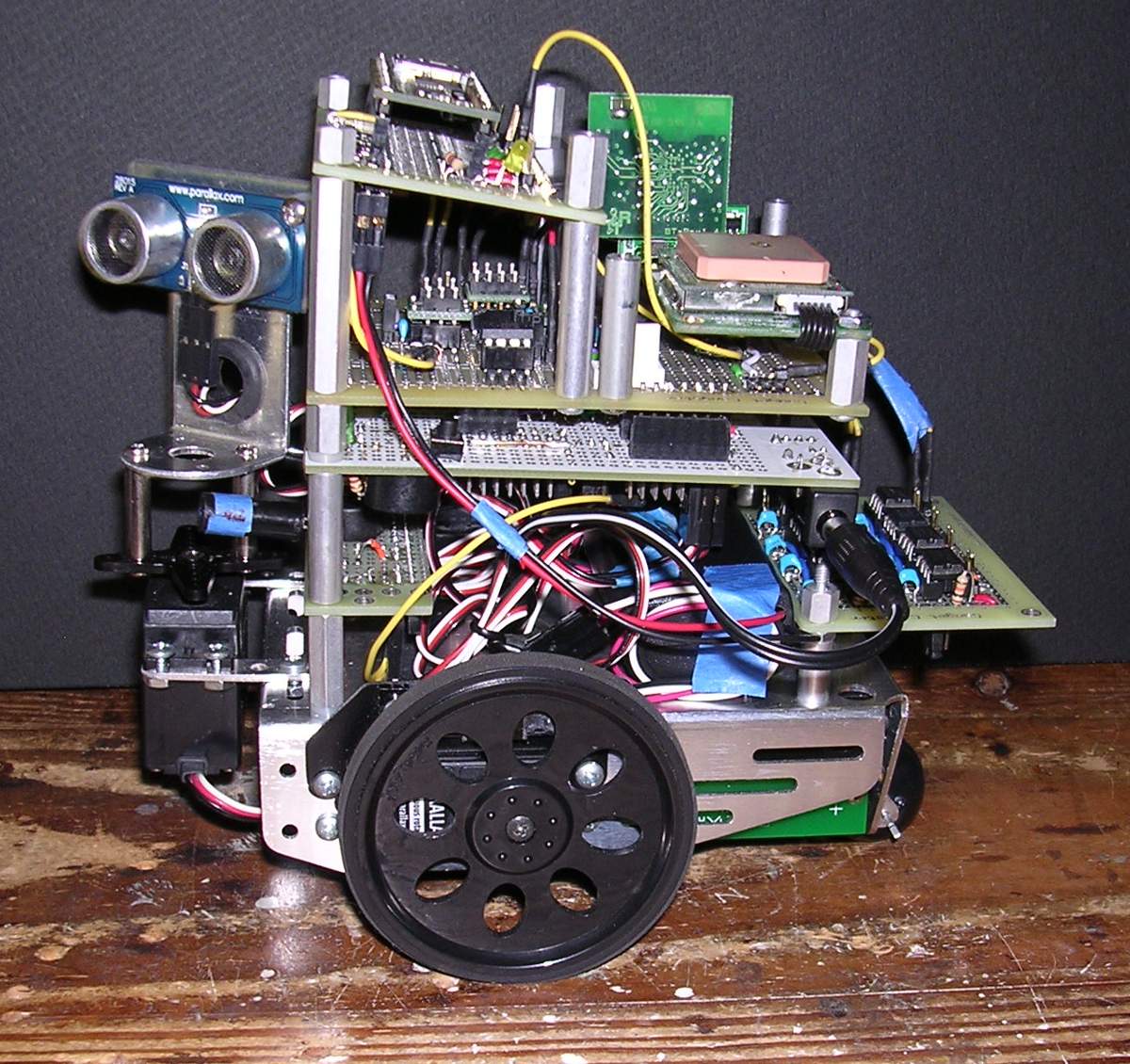
Figure 1 shows a configured Boe-Bot platform designed to maximize flexibility. The design, which uses the propeller chip as the principal controller, achieves flexibility in three ways.
1. Components (sensors,etc.) are distributed on daughter boards which may be plugged into the master controller board or attached to the boe-bot frame in different configurations suited to specific applications.
2. All prop and sensor I/O pins are made available through male headers, allowing jumper wire connections between prop & sensors in different configurations.
3. The mother board eeprom is replaced with a memory card containing 7 eeproms, each individually selectable. This board can store up to 7 different programs, thus minimizing the need to reprogram the eeprom whenever the bot configuration or application is changed, since only one eeprom can be active at a time.
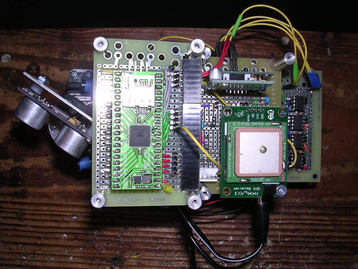
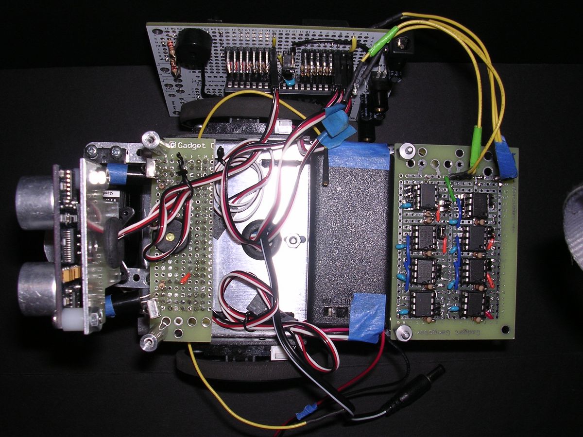
The configuration shown in Figure 1 (side view) has five boards: a mother & 4 daughter boards.· Figure·2 shows a top view in which the topmost daughter board is a coprocessor card. A Propmodule occupies the half Gadget Gangster board, adding an SD card facility and 24 additional pins to the bot.··One of these pins is shown connected to the GPS module attached to the lower daughter (full Gadget Gangster) board. The addition of a 2nd propeller to the bot increases the capability to deal with data acquisition tasks such as vision analysis as well as reduce the burden on the primary propeller in handling multiple sensors.
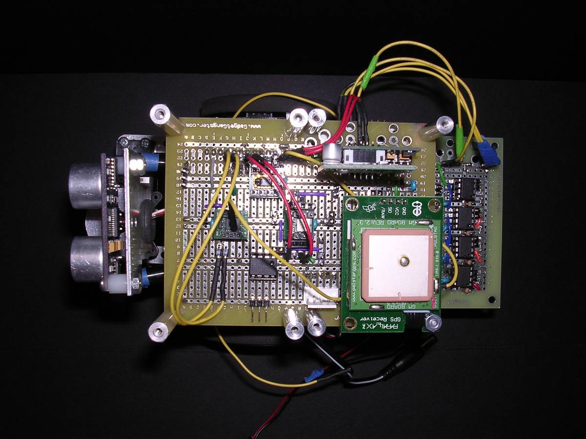
Removing the top board exposes the sensor daughter board (Figure 3) which is plugged into the mother board.·Besides the GPS module, this board is populated with the Easy Bluetooth, HM55B Compass, Sensirion SHT11, DS1302·Clock, and MX2125 2-Axis Accelerometer modules. Provision is also made to use the·H48C 3-Axis accelerometer·instead of the 2-axis version. Jumper wires are shown connecting the various sensors ·with the 11 pins available·from the mother board.
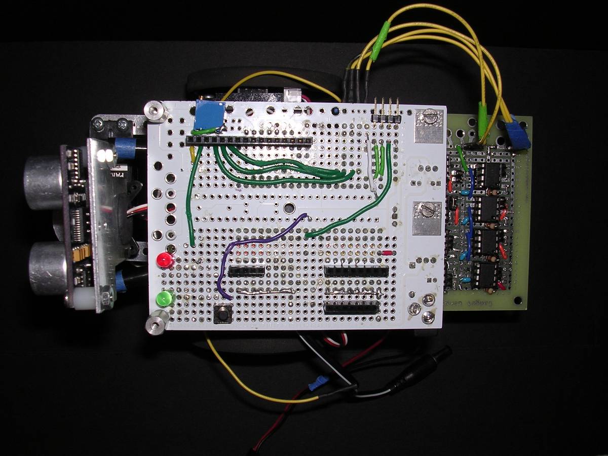
The mother board is revealed when the daughter board is unplugged (Figure 4). It consists of a modified version of BrandonC's ·Propeller Robot Module (see Gadget Gangster website).· The bottom of this board is the top in the bot. A·female header at the top left side is the receptacle for full size daughter boards, providing power and access to 11 prop pins.· Servo and other connections (eg, the·Ping),·are made to to 16 pins accessible from the bottom (bot) side.· Removing the mother board shows the robot base (Figure 5), revealing the attached memory card in the rear·which is connected to the I2C bus on the mother board.· The memory card also contains an optional 2 MB flash ram chip. ·IR units (led & detectors) occupy· the small front daughter board.· An auxiliary power supply for the PropModule is also placed on the base.
The next two posts in this thread will be used to describe the hardware features of the boe-bot version in·greater detail and the software objects used to test the system at a later date.


Comments
Mother Board· (motherbrd.jpg)
BrandonC's Robot Propeller Module (Gadget Gangster) was modified for use in the BOE-BOT design outlined in the previous post. The specific changes in the module are indicated by the red X's on the figure.
· 1) The 5 volt power to pin arrays was separated between the servo and sensor pins, allowing selection of Vin or regulated 5V to operate the servos. The jumper block is shown enabling the 5V power source for both servo & sensor pin arrays.
· 2) 1K resistors were placed in line with 4 of the sensor pins to facilitate connection of 5V devices such as PING to the propeller.
· 3)·A piezospeaker was added (wired to P24), as well as 2 leds and a reset switch.
· 4) The I2C bus in the form of a 4 pin male header was added for connection to the memory card.
· 5) A 16 pin female header was used to accomodate the 2x16 parallel LCD or a plugin daughter board. The header at the bottom of the board is used to provide stability to the daughter board plugin. The other 2 headers allow access to servo & sensor pins.
Memory Card (MemoryBrd.jpg)
Each of the seven eeproms (E1-E7) are set to a unique address (other than 0) using 10K pullup resistors. A specific eeprom is selected for loading programs by inserting a jumper block in the male header associate with the prom, thereby, setting its address to 0.· E3 is shown selected in the figure. Currently, E1 is a 64K and E2-E7 a 32K eeprom. E1 could be used for temporary data storage rather than program storage. Note that E1 is wired to the power bus (bottom view), while all the other proms require jumper blocks to connect to power, reducing the drain on the bot batteries if all the chips were powered. Power·and I2C bus (SDA/SCL) connection headers are on the right side.·
The chip in the upper right corner is a WinBond W25X126 2MB flash memory. Its use requires 4 pins: /CS, DO, DIO, & CLK.
In retrospect, I over designed the memory card.· Each of the eeporoms could be identically set at address 0 and individually selected by connecting to power.
Sensor Board (SensorBrd.jpg)
The sensor board (full gadget gangster) enables the following sensors and/or modules:·(1) Hitachi HM55B compass, (2) Sensirion SHT-11 humidity & temperature, (3) Memsic dual accelerometer MX2125 or optional Hitachi H48C 3 axis accelerometer, (4) Dallas DS1302 timekeeping chip, (5) Easy Bluetooth Module, and (6)·GPS receiver.
The module data·I/O pins are identified on the figure (zoom in). Jumper blocks are labeled: A -·HM55B 3.3V power, B - SHT-11 3.3V power, C - DS1302 3.3V power, D - H48C required connection of P5 to ground,·E - MX2125 3.3V power, F - H48C optional 5V power, and G - sets GPS to processed data output.· Power jumper blocks may be removed to disable·dip modules. Note that SHT-11 pins 1 & 3 are connected to prop pins 21 & 19.
The male header (top left)·allows access to prop pins 27, 26, 25, and 23 - 16. Additional male headers·include an auxiliary 1-pin port with power and a 5-pin (prop 27,26,25,23 & 18)·port for possible connection to an additional mother board.· The bottom view shows the headers wich plug into the mother board.
Co-Processor Board (CoProcBrd.jpg)
A propModule_ps_us_sd is plugged into female headers on a half gadget gangster board. Pins 5-15 are acessed through right-angle male headers on the bottom. Pins 16-27 are accessed either through straight male headers·or 3·Digilent style sockets (3.3V, grd & 4 pins).· The prob Module can be powered from 3.3V, 5V, or·a 3V (2 AA lithium batteries) auxiliary power supply on the bot. The co-processor has a Parallax prop-plug programming port and a microSD card reader.
Bot Front View (FrontView.jpg)
This view of the bot shows the placement of the Ping sensor as well as other additions.· Note the microswitch bumpers and IR distance sensors, each easily adjusted to different orientations, placed on each side of the bot. A photo-resistor ( light seeker)·and MLX90614 thermometer module (heat seeker) are attached to the ping brackets.
Post Edited (ngl) : 9/11/2009 4:58:55 AM GMT
The attached figure shows a side view of what I call my Phase I Bot.· It is configured using only the master control and memory boards (see previous post).· The bot includes an ir remote detector, a ·Ping, a single photoresistor attached to the ping servo, bumpers, ir headlight-detectors, encoders, and a single QTI ir reflectance detector attached to the bot's bottom.· The ir remote is used as the master controller, not only to operate the bot, but also to select from 6 different autonomous·roaming modes. ·The attached spin program exercises all these operational modes. It is stored in eeprom E2. Further details are described in the software.
Nick
Post Edited (ngl) : 10/20/2009 4:46:30 AM GMT
I like some of the modifications you made! I notice you added some resistors to the sensor side of the headers. what are they used for? Good idea putting the mounting hardware on the regulators. I was kinda looking for a place to mount the board to a robot.
If your BOE-bot works, I would love to see a video.
Brandon C.
▔▔▔▔▔▔▔▔▔▔▔▔▔▔▔▔▔▔▔▔▔▔▔▔
No purchase necessary. See back panel for more details.
Tired of the same old robot brains? not enough processing power? Get the Propeller Robot Module now!!
Post Edited (Brandon C.) : 9/2/2009 8:49:26 PM GMT
Nick
▔▔▔▔▔▔▔▔▔▔▔▔▔▔▔▔▔▔▔▔▔▔▔▔
"When the government is afraid of the people there is liberty, when the people are afraid of the government, there is tryanny"
·Thomas Jefferson
Great job on your bot.
I have a question about your Memory card, Can you tell me more about it.
I was thinking about building one for my propeller however before I do that I was looking at other ideas and options.
Rob
This is one of the most outstanding BoeBot projects I have ever seen!
What you have accomplished with the add on customized boards is
totally awesome! Your integrated use of sensors is outstanding. It
will be lots of fun to program this robot!
Where are the schematics? You should really draw up the wiring
diagrams to preserve this robot. You will be happy you did when
looking back on this project. Do you have a list of applications?
What is it designed to accomplish? Keep up your fine work and
accomplishments!
▔▔▔▔▔▔▔▔▔▔▔▔▔▔▔▔▔▔▔▔▔▔▔▔
humanoido
*Stamp SEED Supercomputer *Basic Stamp Supercomputer *TriCore Stamp Supercomputer
*Minuscule Stamp Supercomputer *Tiny Stamp Supercomputer *Penguin with 12 Brains
*BASIC Stamp Supercomputing Book *Three Dimensional Computer *StampOne News!
*Penguin Tech *Penguin Robot Society *Toddler Humanoid Robot Project
*Ultimate List Prop Languages *Prop-a-Lot *Prop SC Computer - coming soon!
*Prop IB Hypercomputer - under development *Robotic Space Program