

GPS Datalogger (Using Google Earth)
 Chris Savage
Parallax EngineeringPosts: 14,406
Chris Savage
Parallax EngineeringPosts: 14,406
GPS Datalogger – by Chris Savage
·
There are plenty of projects out there that deal with GPS and microcontrollers, many of which make use of the data for such things as navigation.· The Robo-Magellan competition is one such application.· But what if you wanted to visualize the path your robot took through such a course?· Better yet, what if you wanted to log the path of a bike or car trip?· Sure, you could export the data for processing into some other application that does this, but you could also make use of a very popular application called Google™ Earth.
·
Plotting a Course
·
Google Earth is a virtual globe program that can show you, at a continent, state, city or even street level, various locations on the planet, including satellite images.· You can follow streets as well as see popular locations.· From within Google Earth, I can see my house, including the garden in the back yard.· You can even see a close-up of Parallax, Inc.· One interesting thing about Google Earth is it is available free and supports Keyhole Markup Language (KML) which is an XML-based language for expressing geographic annotation, maps and even 3D objects.· One feature of KML is the ability to plot a path using GPS coordinates.· So if you have a source of coordinates, such as a GPS module, you can create a KML file with a little help from a BASIC Stamp® microcontroller module and a Parallax Memory Stick Datalogger.
·
Data Portability
·
On a PC with Google Earth installed you need only double-click a KML file and Google Earth will launch and plot the data.· The trick is getting the data from your mobile GPS system into the PC in the correct format.· Parallax manufactures a Memory Stick Datalogger, which is essentially a USB host bridge using the Vinculum chip from FTDI.· The Memory Stick Datalogger allows you to use a portable storage device such as a USB thumb drive to store the GPS data.· Since the FAT file system is supported, you can save the file in the native format and it will be directly readable by the PC and Google Earth.· Since KML is an XML-based language there are a lot of tags similar to those used in HTML.· For now we’ll simplify things by saying that the important parts of the file we are creating are pretty much always going to be the same.
·
Decoding KML
·
Google has an extensive specification for KML at http://earth.google.com so I won’t go into all the details.· The language is very powerful and warrants a look if you’re interested in creating files for Google Earth.· For our purposes we will only want to create paths.· In order to do this we will need three pieces of information.· First we will need what I call the header information.· This is essentially all the information Google Earth will need to know, such as the version of the language, source URL, line types and colors, mode, etc.
·
Next we need the coordinates themselves.· Oddly Google Earth expects the data as Longitude, Latitude then Altitude.· Conversely, http://maps.google.com uses Latitude then Longitude.· In any event this will be the part of the data we will be supplying as we go.· Finally the file will need the closing tags, or what I call the footer data.· The trick now is to get a BASIC Stamp to put all this data onto a USB thumb drive in a format so it can be read by a PC using Google Earth.
·
BASIC Approach to KML
·
The BASIC Stamp module has 2K of EEPROM available for program and data.· I originally tested the concept of doing this by hard-coding the data into SEROUT statements. However, this left no room for making the program do anything other than writing the data straight from the GPS Module.· I decided to create a data table in EEPROM of all the header data used to create the KML file.· In order to do this, quotation marks had to be coded into ASCII values since quotes are used to enclose text used by the KML file.· To trim a few more bytes instead of using a CRLF for each line I used a single null (zero) byte and had the program replace that whenever encountered.· I also needed to be able to change the altitude mode easily.· I tried several methods but ultimately decided to hard code the text section of that one command based on a mode constant being 0 or 1.· Since this creates a break in the header block I used the value 255 to separate blocks of KML code.· When the subroutines read the 255 they terminate and return so the program can write out the next block of data to the Datalogger.
·
The program is very straightforward and includes many pieces of code from other programs I have written for the various hardware used.· The Parallax Memory Stick Datalogger and Parallax GPS Modules are used so the first thing that happens is the program initializes and establishes communication with the Datalogger.· A bi-color LED is used to indicate status and blinks green while the Datalogger is initialized.· If no USB drive is connected the program will wait until it is connected before moving on.· Once the Datalogger is initialized and the drive is identified the program will write out the KML header data.· This will take several seconds since it is being read byte-by-byte from EEPROM and written out to the drive.· While this is happening the LED will be fast- blinking red.
·
Once the data is written the program will attempt to get the satellite signal status from the GPS module to see if the signal is valid.· During this the LED will slow-blink red.· Once the satellite signal is valid the LED will turn solid green to indicate that the system is ready to start logging data.· There are two pushbuttons on the GPS Datalogger Board.· Pressing the first one until the LED turns red will start the logging process.· The GPS Datalogger writes data to the USB drive at a fixed rate of about 1 sample every 3 seconds.· If the GPS signal is lost during logging, the last coordinates are written at the same rate.· This makes it possible to determine how long the data was accumulated, even during times when the signal is not valid.
·
At any time once the USB drive has been initialized you can hold down the second button until the LED starts blinking red.· This will write out the KML footer data and close the file.· When it is safe to remove the USB drive the LED will blink red/green alternately.· It is not advisable to remove it at any point before this since corruption of the data or even the file system is possible.· This means you probably would have to reformat the USB drive.
·
I took a short drive around the vicinity of Parallax.· A screenshot of the Google Earth plot of my journey is shown in Figure 1.· The KML file of this trip can be downloaded with the source code and is called LOGDATA.KML.· You can load it into Google Earth for a look at my trip or you can open it using Notepad to see the structure of the KML data.· Note that due to the margin of error in accuracy of GPS as well as differences in the Google Earth terrain map, at some points it looks like I was driving off the road or in the oncoming lane.· Rest assured I was driving safely.

Figure 1 - This is a screenshot from Google Earth of my trip around Parallax Inc.·
Building the GPS Datalogger
·
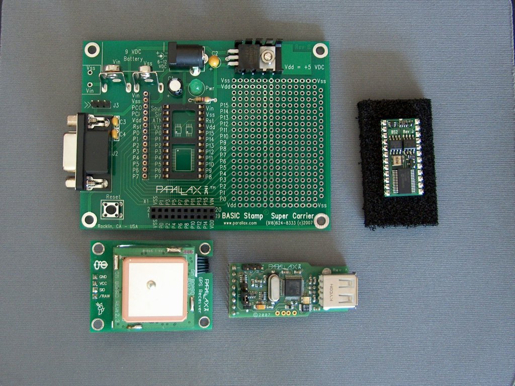
Figure 2 (attached at the end of this message) shows the schematic for the GPS Datalogger, but to simplify building the prototypes I used the Parallax Super Carrier Board.· A complete parts list is included in Listing 1.· Figure 3 (attached at the end of this message) shows the main components that make up the logger.· In Figure 4 (attached at the end of this message) you can see that I have pre-drilled a mounting hole for the GPS Module and installed a 4-pin SIP socket.· While not required, this is recommended.· You will also need a ½” threaded standoff between the board and the GPS Module.· A rubber foot from the Super Carrier Board was cut in half and used as a pad to hold up one end of the Memory Stick Datalogger so that there is extra support when inserting a USB drive into it.
·
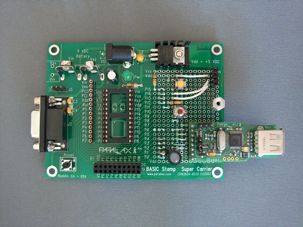
Figure 5 (attached at the end of this message) shows the remaining support components as well as the Memory Stick Datalogger module installed on the Super Carrier Board.· At this point it is a good idea to run the test programs included in the source code package.· I will often want to test individual subsystems of a project while building it to simplify debugging if there is an issue.· There are programs for testing the GPS, Datalogger, LED and buttons.· The GPSTest.bs2 file is a modified version of the GPS Demo program.· The DataloggerTest.bs2 file is a modified version of the Datalogger Demo program and the ButtonLEDTest.bs2 program was quickly written for the purposes of testing those components.· Downloading the ButtonLEDTest.bs2 program will blink the bi-color LED red 5 times, green 5 times, then alternate red/green 5 times.· After that it will report whenever either of the buttons is pressed.· You should run these programs to make sure all the hardware is functioning before moving on.
Final Assembly

Figure 6 - The completed prototype on standoffs.
Figure 6 shows the completed assembly.· If you plan on installing standoffs on the Super Carrier Board as I did, you will want to make sure you do this before securing the GPS Module as it will block one of the holes.· Once everything is assembled you can download GPS Datalogger V1.0.bs2 and start logging data.· The Super Carrier Board powers everything from its own 5 volt regulator, so for testing I used a cable which plugs into a cigarette lighter or auxiliary connector in a car and then powers the board.· Placing the board up in the center of the dashboard nearest the window gave the best results and I never lost my signal.· Be sure not to obstruct your view when placing the unit up near the window.
·
During the test I did have to grab the unit several times to keep it from flying one way or another, so my advice is if you’re going to test it like I did, get some Velcro® or temporarily tape it in place.· The whole system consumes about 200 mA of current depending on the USB drive used.· This causes the voltage regulator on the Super Carrier Board to become quite warm.· Be careful of grabbing the board near the regulator.· Another note about this is due to current consumption this unit cannot be powered from a 9 volt battery.· You will need a high capacity power source, or if used in a car or motorcycle you can use the cigarette lighter or auxiliary connector and you should be okay.· For a bicycle a generator may even be possible.
·
Final Thoughts
·
The code as included uses all but 6 bytes of the EEPROM space.· One of the main reasons is my very verbose DEBUG statements, which are not needed and can be taken or commented out.· Many people like to see some feedback when testing things for the first time and I was inclined to provide that although DEBUG statements (or anything with added text) use a lot of program memory.
·
Note that by default the data logged ignores elevation (altitude) data.· If you wish to enable this you can change the mode constant toward the beginning of the program from 0 to 1.· Be warned that GPS modules don’t always match the elevation maps used by Google Earth and this can sometimes cause your path to disappear under the terrain, making it invisible.· This will cause breaks in the path.· I also noted sometimes it looked like I was several meters above the ground (must be my flying car).· You can also change the mode in the KML file directly by using notepad.· If you change the word ‘clampToGround’ to ‘absolute’ and reload it into Google Earth it will now show altitude data.· This data is shown as a line extruded from the virtual ground.
·
Two buttons were not required in this project, but I wanted to add some flexibility to the hardware for those I know are going to do more with this.· A few possible applications would be tracking a child driver when borrowing the family car.· The original design that I created used a BS2p and was installed in a vehicle with a P-Channel MOSFET to control power to the GPS and Datalogger.· The BS2p module was powered from the battery power directly.· When the ignition was turned on the system would create a new file (sequentially numbered) and start logging data.· Once the ignition was turned off the system would write out the footer data, close the file and shut down the GPS and Datalogger.· I chose to create a simpler version for this article to make it easier to see how this task could be accomplished and because several people had mentioned that the BASIC Stamp 2 would not have the resources to do this.
·
Currently time/date stamping is not supported, but in reviewing the KML specifications it seems it is available as an option to use that data and it is readily available from the GPS Module.· Perhaps we will see what some of you come up with.· You can post your changes here to the project page on the Parallax Support/Discussion Forums.· Take care!
▔▔▔▔▔▔▔▔▔▔▔▔▔▔▔▔▔▔▔▔▔▔▔▔
Chris Savage
Parallax Engineering
50 72 6F 6A 65 63 74 20 53 69 74 65
Post Edited (Chris Savage (Parallax)) : 9/5/2009 5:16:16 AM GMT
·
There are plenty of projects out there that deal with GPS and microcontrollers, many of which make use of the data for such things as navigation.· The Robo-Magellan competition is one such application.· But what if you wanted to visualize the path your robot took through such a course?· Better yet, what if you wanted to log the path of a bike or car trip?· Sure, you could export the data for processing into some other application that does this, but you could also make use of a very popular application called Google™ Earth.
·
Plotting a Course
·
Google Earth is a virtual globe program that can show you, at a continent, state, city or even street level, various locations on the planet, including satellite images.· You can follow streets as well as see popular locations.· From within Google Earth, I can see my house, including the garden in the back yard.· You can even see a close-up of Parallax, Inc.· One interesting thing about Google Earth is it is available free and supports Keyhole Markup Language (KML) which is an XML-based language for expressing geographic annotation, maps and even 3D objects.· One feature of KML is the ability to plot a path using GPS coordinates.· So if you have a source of coordinates, such as a GPS module, you can create a KML file with a little help from a BASIC Stamp® microcontroller module and a Parallax Memory Stick Datalogger.
·
Data Portability
·
On a PC with Google Earth installed you need only double-click a KML file and Google Earth will launch and plot the data.· The trick is getting the data from your mobile GPS system into the PC in the correct format.· Parallax manufactures a Memory Stick Datalogger, which is essentially a USB host bridge using the Vinculum chip from FTDI.· The Memory Stick Datalogger allows you to use a portable storage device such as a USB thumb drive to store the GPS data.· Since the FAT file system is supported, you can save the file in the native format and it will be directly readable by the PC and Google Earth.· Since KML is an XML-based language there are a lot of tags similar to those used in HTML.· For now we’ll simplify things by saying that the important parts of the file we are creating are pretty much always going to be the same.
·
Decoding KML
·
Google has an extensive specification for KML at http://earth.google.com so I won’t go into all the details.· The language is very powerful and warrants a look if you’re interested in creating files for Google Earth.· For our purposes we will only want to create paths.· In order to do this we will need three pieces of information.· First we will need what I call the header information.· This is essentially all the information Google Earth will need to know, such as the version of the language, source URL, line types and colors, mode, etc.
·
Next we need the coordinates themselves.· Oddly Google Earth expects the data as Longitude, Latitude then Altitude.· Conversely, http://maps.google.com uses Latitude then Longitude.· In any event this will be the part of the data we will be supplying as we go.· Finally the file will need the closing tags, or what I call the footer data.· The trick now is to get a BASIC Stamp to put all this data onto a USB thumb drive in a format so it can be read by a PC using Google Earth.
·
BASIC Approach to KML
·
The BASIC Stamp module has 2K of EEPROM available for program and data.· I originally tested the concept of doing this by hard-coding the data into SEROUT statements. However, this left no room for making the program do anything other than writing the data straight from the GPS Module.· I decided to create a data table in EEPROM of all the header data used to create the KML file.· In order to do this, quotation marks had to be coded into ASCII values since quotes are used to enclose text used by the KML file.· To trim a few more bytes instead of using a CRLF for each line I used a single null (zero) byte and had the program replace that whenever encountered.· I also needed to be able to change the altitude mode easily.· I tried several methods but ultimately decided to hard code the text section of that one command based on a mode constant being 0 or 1.· Since this creates a break in the header block I used the value 255 to separate blocks of KML code.· When the subroutines read the 255 they terminate and return so the program can write out the next block of data to the Datalogger.
·
The program is very straightforward and includes many pieces of code from other programs I have written for the various hardware used.· The Parallax Memory Stick Datalogger and Parallax GPS Modules are used so the first thing that happens is the program initializes and establishes communication with the Datalogger.· A bi-color LED is used to indicate status and blinks green while the Datalogger is initialized.· If no USB drive is connected the program will wait until it is connected before moving on.· Once the Datalogger is initialized and the drive is identified the program will write out the KML header data.· This will take several seconds since it is being read byte-by-byte from EEPROM and written out to the drive.· While this is happening the LED will be fast- blinking red.
·
Once the data is written the program will attempt to get the satellite signal status from the GPS module to see if the signal is valid.· During this the LED will slow-blink red.· Once the satellite signal is valid the LED will turn solid green to indicate that the system is ready to start logging data.· There are two pushbuttons on the GPS Datalogger Board.· Pressing the first one until the LED turns red will start the logging process.· The GPS Datalogger writes data to the USB drive at a fixed rate of about 1 sample every 3 seconds.· If the GPS signal is lost during logging, the last coordinates are written at the same rate.· This makes it possible to determine how long the data was accumulated, even during times when the signal is not valid.
·
At any time once the USB drive has been initialized you can hold down the second button until the LED starts blinking red.· This will write out the KML footer data and close the file.· When it is safe to remove the USB drive the LED will blink red/green alternately.· It is not advisable to remove it at any point before this since corruption of the data or even the file system is possible.· This means you probably would have to reformat the USB drive.
·
I took a short drive around the vicinity of Parallax.· A screenshot of the Google Earth plot of my journey is shown in Figure 1.· The KML file of this trip can be downloaded with the source code and is called LOGDATA.KML.· You can load it into Google Earth for a look at my trip or you can open it using Notepad to see the structure of the KML data.· Note that due to the margin of error in accuracy of GPS as well as differences in the Google Earth terrain map, at some points it looks like I was driving off the road or in the oncoming lane.· Rest assured I was driving safely.
Figure 1 - This is a screenshot from Google Earth of my trip around Parallax Inc.·
Building the GPS Datalogger
·
Figure 2 (attached at the end of this message) shows the schematic for the GPS Datalogger, but to simplify building the prototypes I used the Parallax Super Carrier Board.· A complete parts list is included in Listing 1.· Figure 3 (attached at the end of this message) shows the main components that make up the logger.· In Figure 4 (attached at the end of this message) you can see that I have pre-drilled a mounting hole for the GPS Module and installed a 4-pin SIP socket.· While not required, this is recommended.· You will also need a ½” threaded standoff between the board and the GPS Module.· A rubber foot from the Super Carrier Board was cut in half and used as a pad to hold up one end of the Memory Stick Datalogger so that there is extra support when inserting a USB drive into it.
·
Figure 5 (attached at the end of this message) shows the remaining support components as well as the Memory Stick Datalogger module installed on the Super Carrier Board.· At this point it is a good idea to run the test programs included in the source code package.· I will often want to test individual subsystems of a project while building it to simplify debugging if there is an issue.· There are programs for testing the GPS, Datalogger, LED and buttons.· The GPSTest.bs2 file is a modified version of the GPS Demo program.· The DataloggerTest.bs2 file is a modified version of the Datalogger Demo program and the ButtonLEDTest.bs2 program was quickly written for the purposes of testing those components.· Downloading the ButtonLEDTest.bs2 program will blink the bi-color LED red 5 times, green 5 times, then alternate red/green 5 times.· After that it will report whenever either of the buttons is pressed.· You should run these programs to make sure all the hardware is functioning before moving on.
Final Assembly
Figure 6 - The completed prototype on standoffs.
Figure 6 shows the completed assembly.· If you plan on installing standoffs on the Super Carrier Board as I did, you will want to make sure you do this before securing the GPS Module as it will block one of the holes.· Once everything is assembled you can download GPS Datalogger V1.0.bs2 and start logging data.· The Super Carrier Board powers everything from its own 5 volt regulator, so for testing I used a cable which plugs into a cigarette lighter or auxiliary connector in a car and then powers the board.· Placing the board up in the center of the dashboard nearest the window gave the best results and I never lost my signal.· Be sure not to obstruct your view when placing the unit up near the window.
·
During the test I did have to grab the unit several times to keep it from flying one way or another, so my advice is if you’re going to test it like I did, get some Velcro® or temporarily tape it in place.· The whole system consumes about 200 mA of current depending on the USB drive used.· This causes the voltage regulator on the Super Carrier Board to become quite warm.· Be careful of grabbing the board near the regulator.· Another note about this is due to current consumption this unit cannot be powered from a 9 volt battery.· You will need a high capacity power source, or if used in a car or motorcycle you can use the cigarette lighter or auxiliary connector and you should be okay.· For a bicycle a generator may even be possible.
·
Final Thoughts
·
The code as included uses all but 6 bytes of the EEPROM space.· One of the main reasons is my very verbose DEBUG statements, which are not needed and can be taken or commented out.· Many people like to see some feedback when testing things for the first time and I was inclined to provide that although DEBUG statements (or anything with added text) use a lot of program memory.
·
Note that by default the data logged ignores elevation (altitude) data.· If you wish to enable this you can change the mode constant toward the beginning of the program from 0 to 1.· Be warned that GPS modules don’t always match the elevation maps used by Google Earth and this can sometimes cause your path to disappear under the terrain, making it invisible.· This will cause breaks in the path.· I also noted sometimes it looked like I was several meters above the ground (must be my flying car).· You can also change the mode in the KML file directly by using notepad.· If you change the word ‘clampToGround’ to ‘absolute’ and reload it into Google Earth it will now show altitude data.· This data is shown as a line extruded from the virtual ground.
·
Two buttons were not required in this project, but I wanted to add some flexibility to the hardware for those I know are going to do more with this.· A few possible applications would be tracking a child driver when borrowing the family car.· The original design that I created used a BS2p and was installed in a vehicle with a P-Channel MOSFET to control power to the GPS and Datalogger.· The BS2p module was powered from the battery power directly.· When the ignition was turned on the system would create a new file (sequentially numbered) and start logging data.· Once the ignition was turned off the system would write out the footer data, close the file and shut down the GPS and Datalogger.· I chose to create a simpler version for this article to make it easier to see how this task could be accomplished and because several people had mentioned that the BASIC Stamp 2 would not have the resources to do this.
·
Currently time/date stamping is not supported, but in reviewing the KML specifications it seems it is available as an option to use that data and it is readily available from the GPS Module.· Perhaps we will see what some of you come up with.· You can post your changes here to the project page on the Parallax Support/Discussion Forums.· Take care!
▔▔▔▔▔▔▔▔▔▔▔▔▔▔▔▔▔▔▔▔▔▔▔▔
Chris Savage
Parallax Engineering
50 72 6F 6A 65 63 74 20 53 69 74 65
Post Edited (Chris Savage (Parallax)) : 9/5/2009 5:16:16 AM GMT

1049 x 841 - 814K

3060 x 2310 - 786K
1024 x 768 - 226K

1024 x 768 - 269K
1024 x 766 - 271K
Comments
Figure 7 - The·two prototypes after testing.
PARTS LIST (w/Parallax Part Numbers)
(1) Super Carrier Board (#27130)
(1) BASIC Stamp 2 Module (#BS2-IC)
(1) GPS Module (#28146)
(1) Memorystick Datalogger (#27937)
(2) 10K Resistors (#150-01030)
(1) 220 Ohm Resistor (#150-02210)
(2) Tact Switch (#400-00002)
(1) Bi-Color LED (#350-00005)
OPTIONAL COMPONENTS
(1) Rubber Foot (Included with Super Carrier Board)
(1) 1/2" Threaded Standoff (F-F, 4-40)
(2) 4-40, 1/4" Screw (#700-00028)
(1) 4-pin SIP Socket (#450-00401)
(1) LED Standoff (#350-90000)
▔▔▔▔▔▔▔▔▔▔▔▔▔▔▔▔▔▔▔▔▔▔▔▔
Chris Savage
Parallax Engineering
50 72 6F 6A 65 63 74 20 53 69 74 65
Post Edited (Chris Savage (Parallax)) : 8/27/2009 4:50:52 PM GMT
Great project! "I love it"
I would like to use a project like this to verify my location coordinates when I take out my Celestron CPC 1100 telescope when I am under the stars.
With this, I can track my route and see my location when I get there. Very Cool!
Post Edited (Rob7) : 8/28/2009 3:00:49 AM GMT
Can you add altitude for driving up the side of a mountain?
humanoido
Post Edited (humanoido) : 8/28/2009 6:08:31 AM GMT
Altitude is already supported…the article mentions a constant you change in the code which will enable Google Earth to display the altitude you were at (according to the GPS) for each point. You can see these measurements in the resulting KML file. Take care.
@All,
As a side note, this project is actually pared down from the original application which was to track a student driver. The original project was mostly the same except a BS2p was used and the board was mounted inside the dash of the vehicle. It was powered all the time from the battery power with an opto coupled to the ignition line to sense when the vehicle was turned on. The GPS and Datalogger had their power controlled via P-Channel MOSFETs and were off normally. When the ignition would turn on the system would turn on the Datalogger, wait for initialization and then power the GPS module and await a lock. A new file was opened each time the vehicle was started using a sequential file number incremented each time. When the vehicle was turned off the BS2p would write out the footer data, turn off the GPS and Datalogger and wait for ignition again. This kept power consumption down to a minimum. At some point I may post the project.
▔▔▔▔▔▔▔▔▔▔▔▔▔▔▔▔▔▔▔▔▔▔▔▔
Chris Savage
Parallax Engineering
50 72 6F 6A 65 63 74 20 53 69 74 65
·
Chris,
First off, thanks for pulling together this excellent project. It contains two elements of great interest to me. And I never would have thought one could format GPS data for direct entry into Google Earth.
A couple of questions/comments:
What is the purpose of the constant "NumSamples"? [noparse][[/noparse]The editor could not find any reference to it in the program.] Was it to be used to 'smooth' data?
The styling of the program to fit the capability of the basic model of the BS2 is especially creative. But how would one go about taking advantage of the multibank models of the Basic Stamp in order to expand the data entries? I wish to add vehicle speed and data from a barometric pressure altimeter; needing significantly more programming space.
By-the-way, several months ago you mentioned that you were working on a pressure sensor module. Any update on this product?
Again, thanks for a neat project.
cheers, David
NumSamples is an artifact left over from when I pared this program down from its original implementation mentioned above. I often reuse code in my projects and apparently forgot to remove that consant. As for the sensor, that should be available soon. I don’t have any definite data for you though. Take care.
▔▔▔▔▔▔▔▔▔▔▔▔▔▔▔▔▔▔▔▔▔▔▔▔
Chris Savage
Parallax Engineering
50 72 6F 6A 65 63 74 20 53 69 74 65
·
Hope that helps.
Jim
Post Edited (hover1) : 9/1/2009 9:17:14 PM GMT
▔▔▔▔▔▔▔▔▔▔▔▔▔▔▔▔▔▔▔▔▔▔▔▔
Chris Savage
Parallax Engineering
50 72 6F 6A 65 63 74 20 53 69 74 65
·
I would also like to ask some questions very important for me:
Could I·use the data form the datalogger in a program other than Google Earth? (can you propose me one?) The reason I want to do this·is to keep absolute track of the position of my Boebot when I give it directions to follow a certain path, and then compare the path with the curve I used for input. Since I read the article I was thinking to use some kind of a pen so to mark the path and then compare the trajectory with a plotted curve. And now comes the second question about the resolution of the gps. Could the module indentify moves in an area·of about 1m2 -·4m2?
Thank you.
The neat thing about the data logger module is that you can write the file out in any format you want. For example…on another data logger project I am working on for solar energy, the data logger writes out a spreadsheet compatible .CSV file. This type of file can be easily imported into any spreadsheet application and used to plot charts and graphs.
To create a CSV file you would simply write out all the fields for each record with a comma in between them and a CR/LF terminating the record. The demo code from our website creates such a file although it is minimum and doesn’t have the extension, it is technically a CSV file inside. I hope this helps. Take care.
▔▔▔▔▔▔▔▔▔▔▔▔▔▔▔▔▔▔▔▔▔▔▔▔
Chris Savage
Parallax Engineering
50 72 6F 6A 65 63 74 20 53 69 74 65
·
▔▔▔▔▔▔▔▔▔▔▔▔▔▔▔▔▔▔▔▔▔▔▔▔
Chris Savage
Parallax Engineering
50 72 6F 6A 65 63 74 20 53 69 74 65
·
this is such a cool project - and a representative combo of some nice Parallax products. Glad to see that the kit is selling well.
Just wondering if you've calculated how long the logger can run --- say if you use one of those mambo 2gig flash sticks?
thanks
- Howard
▔▔▔▔▔▔▔▔▔▔▔▔▔▔▔▔▔▔▔▔▔▔▔▔
I had not made those calculations...but it should be easy enough since the file size is predictable. Take care.
▔▔▔▔▔▔▔▔▔▔▔▔▔▔▔▔▔▔▔▔▔▔▔▔
Chris Savage
Parallax Engineering
50 72 6F 6A 65 63 74 20 53 69 74 65
·
Got the GPS datalogger kit and appreciate all the resources you've assembled here to make the implementation go smoothly.
Unfortunately, I'm trying to log Lat/Long/Heading, and date/time to the memory stick. I have removed some of the Debug code to make room on the EEProm, but There just isn't enough variable RAM space available on the Stamp to log location and Time.
I have some propeller experience, and I was able to find a propeller .spin object for the datalogger. But there doesn't seem to be a parallax-endorsed .spin object for the Parallax GPS reciever module.
Where do I go from here?
I will be writing this data to .csv for importing into database software.
-Ryan
As I pieced together prior program segments I had to do very little clean-up to make this application work on the given resources. Given your needs I would say you could probably squeeze out the extra variable space with a little clean-up. For example, the default buffer size is 10 bytes, but you may be able to get by with 6 freeing up 2 words. I am guessing this can be done looking at the firmware manual for the Vinculum chip. It should work as long as the Vinculum doesn’t send back responses longer than 6 bytes. At startup I think it sends a long string, but you could just call the clear buffer routine as needed to clean that up. Removing the DEBUG statements along with that should buy you the extra space you need.
As I mentioned earlier, this was originally done on a BS2p, in part because of the size of the program. Memory wasn’t an issue there as I was able to store much data in SPRAM. That is another option. As for the Propeller, I haven’t quite gotten to the Datalogger and GPS objects. They’re coming. We’ve recently had an inrush of new products and so I have gotten behind on projects where I would have developed such applications. I am planning on using the Propeller in several upcoming projects as well, so that will see some new objects appearing in the near future. Take care.
▔▔▔▔▔▔▔▔▔▔▔▔▔▔▔▔▔▔▔▔▔▔▔▔
Chris Savage
Parallax Engineering
50 72 6F 6A 65 63 74 20 53 69 74 65
·
Great project, works well.
I use http://www.gpsvisualizer.com/ upload the file and use it.
Quick Question: Some memory stick work and some don't, any ideas?
My KML file:
One thing you can try is updating the firmware on the Datalogger. Nonetheless, some USB drives have firmware that seems to make them incompatible with the Datalogger. I think all Secure Drives are incompatible by default.
▔▔▔▔▔▔▔▔▔▔▔▔▔▔▔▔▔▔▔▔▔▔▔▔
Chris Savage
Parallax Engineering
50 72 6F 6A 65 63 74 20 53 69 74 65
·
I made a little board for the GPS Logger.
I not much of a programmer, and need a little help. Can someone change the code so that GPS can write to a Text file. I change the code where I see the KML Data and KML writing data, but It still writes the KML data after I Save the BS2 file and upload it to the BS2 chip. Any Ideas why it does that?
Also found that the older Verbatim USB drive work.
Is the reset button the same as Power down. BS2 just runs in some loop error.
Post Edited (Triton) : 12/16/2009 6:45:58 AM GMT
To make it write a plain text file (without the KML formatting) you'll want to change the filename extension to .txt, and also figure out how you want to store the data. Probably the easiest would be a line something like this:
You'd want to look at the GPS datasheet for the exact values, since I don't remember whether you get three decimal places or four for decimal minutes (for example).
Reset is not the same as power down. Reset completely clears the BS2 RAM, and restarts the program at the first instruction. Power down would do the same thing without restarting the program at the first instruction.
▔▔▔▔▔▔▔▔▔▔▔▔▔▔▔▔▔▔▔▔▔▔▔▔
Powered by enthusiasm
▔▔▔▔▔▔▔▔▔▔▔▔▔▔▔▔▔▔▔▔▔▔▔▔
Chris Savage
Parallax Engineering
Check out the new Savage Circuits TV!
·
Any ideas why it does that.
Thanks , The board was made a electronics student.
▔▔▔▔▔▔▔▔▔▔▔▔▔▔▔▔▔▔▔▔▔▔▔▔
Powered by enthusiasm
I am working with a BASIC STAMP 2px to control a gyroscope and I am trying to store the data collected using a Data Logger....My problem is that I want to collect and store at least 6000 samples per second and actually I am only getting 3000 samples....I don't know if it is because of the baud rate or what could I do to make it work faster....
My second question is about the energy supplies: I want to use the microcontroller for 8 or 10 gyroscopes and we will collect data for about 20 or 30 minutes....I am not sure if the battery will be able to make it work or I would need any additional source....
Thanks for your help! Is my first robotic experience and I am a little bit lost...
If you're not using the project above you should start a new thread in the Sensors forum.
▔▔▔▔▔▔▔▔▔▔▔▔▔▔▔▔▔▔▔▔▔▔▔▔
Chris Savage
Parallax Engineering
Check out the new Savage Circuits TV!
·
As seen above I also agree that this kit seems to be a great product!!! I'm looking at purchasing one of these kits to put into a FSAE car for some data logging applications. Ultimately once I familiarize myself with this system I was hoping on connecting a XBee 1mW Wire Antenna (XB24-AWI-001) directly into the data logging usb port to send data wirelessly oppose to storing it on board. Could anyone give me insight as to if it would be possible based on the kits current configuration?
Thanks a lot and I look forward to any insight that can be sent my way!
If you wish to transmit the data instead of logging it then you acquire the data from the GPS and send it serially through the XBee. You would have to modify the code but that's pretty easy.· The message before yours doesn't seem to be GPS related at all.· Not sure yet.
▔▔▔▔▔▔▔▔▔▔▔▔▔▔▔▔▔▔▔▔▔▔▔▔
Chris Savage
Parallax Engineering
Check out the new Savage Circuits TV!
·
Some ask for the file use to make my gps board
Hope this is what you are after.
Ciao
I am about to put together the GPS data logger with a BS2P for an upcoming trip of about 3000 miles. I would like to have the ability to make sequential file names instead of erasing the file on power up each time. I cannot find the command to check if the file exists. How would that be done? Can I "Open a File for Reading" and check if I get an error or is there another way of doing that. I also plan to have the power down after closing the file and creating a new file on "Ignition on".
This project did not make it on my trip last year from Houston, Atlanta, LA, Vegas and back home. That would have been a nice one to log as well.
Thanks for a great project
Regards
Chet
▔▔▔▔▔▔▔▔▔▔▔▔▔▔▔▔▔▔▔▔▔▔▔▔
Andrew Williams
WBA Consulting
PowerTwig Dual Output Power Supply Module
My Prop projects: Reverse Geo-Cache Box, Custom Metronome, Micro Plunge Logger