

Power questions
 velociostrich
Posts: 40
velociostrich
Posts: 40
Hi,
I'm working on a project involving an LCD display and five buttons, four
of which are normally-open momentary contact SPST pushbuttons; the fifth
being a SPST toggle switch. Ultimately, I'd like to make my own PCB, but
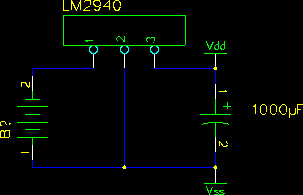
I'm not sure what to do about voltage regulation. Do I just use an LM2940
like on the BOE or will that not be enough? Or is the BS2's on-board
voltage regulator sufficient? The LCD is a 4x20 backlit model -- the one
offered by Parallax.
Using Parallax's BOE schematic as a reference, I drew the attached
schematic -- is this correct?
EDIT: When looking at the schematic for the Serial BOE, Revision C, it seems
as though the positive terminal of the battery is being supplied directly to the
Stamp, instead of letting the LM2940 do all the work; am I correct in this
understanding? So, then, the breadboard offers more Vdd pins than Vin pins
in an effort to prevent the user from overloading the Stamp's less powerful
voltage regulator?
EDIT: Is the heatsink as seen on the BOE (and elsewhere) necessary?
Post Edited (velociostrich) : 8/20/2009 1:03:30 AM GMT
I'm working on a project involving an LCD display and five buttons, four
of which are normally-open momentary contact SPST pushbuttons; the fifth
being a SPST toggle switch. Ultimately, I'd like to make my own PCB, but
I'm not sure what to do about voltage regulation. Do I just use an LM2940
like on the BOE or will that not be enough? Or is the BS2's on-board
voltage regulator sufficient? The LCD is a 4x20 backlit model -- the one
offered by Parallax.
Using Parallax's BOE schematic as a reference, I drew the attached
schematic -- is this correct?
EDIT: When looking at the schematic for the Serial BOE, Revision C, it seems
as though the positive terminal of the battery is being supplied directly to the
Stamp, instead of letting the LM2940 do all the work; am I correct in this
understanding? So, then, the breadboard offers more Vdd pins than Vin pins
in an effort to prevent the user from overloading the Stamp's less powerful
voltage regulator?
EDIT: Is the heatsink as seen on the BOE (and elsewhere) necessary?
Post Edited (velociostrich) : 8/20/2009 1:03:30 AM GMT
303 x 195 - 1K
Comments
Sometimes the heatsink is necessary. It depends on Vin and on the amount of current drawn. If you run the BOE off a 6V supply and draw 1A, that's 1W of power that has to be dissipated from the regulator. It wouldn't get particularly hot even without a heatsink. If you use a 9V supply and draw 1A, that's 4W of power. If you exceed the recommended voltage range and run the BOE off an automotive supply (13.8+V) at 1A, that's 9W of power. The heatsink supplied is likely to get quite hot and the regulator may well go into thermal shutdown.
I'd like very much not to fry my Stamp, as they are rather expensive.