

Transistor Troubles
 zach
Posts: 6
zach
Posts: 6
I am fairly new to practicing electronics, although I have done much reading.
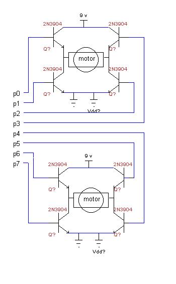
I have the Homework board, and set up a circuit for two motors using a pair of H-Bridges. The motors were powered by the nine volt battery on the homework board.
I currently have each transistor assigned to its own port on the board.
I want to power the motors seperately. From much tinkering, I have found that the only way I can get it to work is by connecting the negative of the 9 V to the Vdd on the board. Both 9 v in the schematic below come from 6 AA batteries. I am unsure of whether I need to add a resistor to the line coming back to Vdd.
Do I need to add a resistor, or is this a good idea at all.
Any other comments would be appreciated.
I have a schematic in TinyCad here...
Post Edited (zach) : 8/17/2009 3:39:24 AM GMT
350 x 566 - 22K
Comments
Try this circuit.
The Vdd is the positive and the Vss is the negative. To apply power to this circuit connect the ground to Vss and the positive to Vin. Aviod the Vdd to power this circuit.
If You have more ?s drop a post reply.
I hope this helps.
_______________$WMc%_________
▔▔▔▔▔▔▔▔▔▔▔▔▔▔▔▔▔▔▔▔▔▔▔▔
The Truth is out there············································ BoogerWoods, FL. USA
Post Edited ($WMc%) : 8/17/2009 4:39:01 AM GMT
A few questions about the schematic.
*What is the purpose of placing the diodes parallel to the transistors?
Does the reverse bias protect the circuit?
*Are the resistors necessary if I am using the I/O pins from the homework board?
I am using HIGH to send the signal which means it sends 5 volts to the transistor base.
*What is the reason for the PNP transistor?
I think that would mean I need to send a LOW signal to that port.
What I have tried so far
I am currently controlling the motors with HIGH and LOW.
Here is a sample script.
HIGH 8
HIGH 10
PAUSE 500
LOW 8
LOW 10
HIGH 9
HIGH 11
PAUSE 500
LOW 9
LOW 11
I have the seme thing set up for 12&14, and 13&15
I have tested the circuit with two motors, one works and one doesn't.
I replaced the unfunctional motor with two diodes in parallel with one reverse biased.
This worked. with 8 and 10 high one flashed. with 9 and 11 the other flashed.
? *What is the purpose of placing the diodes parallel to the transistors?
--Does the reverse bias protect the circuit?
_Yes_
_
? *Are the resistors necessary if I am using the I/O pins from the homework board?
--I am using HIGH to send the signal which means it sends 5 volts to the transistor base.
_
_The Resisters are need to apply enough forward voltage to fully turn on the transistor and also to keep the source current below _the maximum that the $STAMP can supply. witch is ~ 20ma.
_
__A good study of OHMs LAW will help you understand this better. www.12volt.com has a nice OHMs law PIE drawing. down load this and save it. Print this drawing and tape it on your wall. You'll refer to this a lot.
_
? *What is the reason for the PNP transistor?
_
_PNP Transistor's flow current in the opposite direction of a NPN.·· The four transistor arrangement is for use with a signal power supply. A signal power supply is like having one battery. A dual power supply is like having two battery's
_Signal supply________-[noparse][[/noparse]battery]+______________
······························ |····················· |
···························· NEG··· 9volts···· POS
_Dual supply______-[noparse][[/noparse]battery]+____-[noparse][[/noparse]battery]+_______
························· |···················· |···················· |
····················· NEG···· 9volts··· COM··· 9volts·· POS
____$WMc%___________Hope this helps?___
The circuit below·is·just to show use with a dual power supply it needs some refinement as pointed out by Phil.
Sorry if I caused a bunch of confusion!
····················
▔▔▔▔▔▔▔▔▔▔▔▔▔▔▔▔▔▔▔▔▔▔▔▔
The Truth is out there············································ BoogerWoods, FL. USA
Post Edited ($WMc%) : 8/21/2009 2:21:46 AM GMT
-Phil