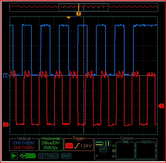
Slight ringing
I have attached an image of the out put of an oscope. one channel has one prop on it the other has another prop on it. both are toggling a pin. As you can see one pin has some noise on it...the board I made, and the other pin has no noise on it...the prop dev board. I was wondering if there are any suggestions for making the output of my board less noise, caps somewher...or such. Another funny thing to note was that the signals slowly moved passed each other as time went by. The props were running the same exact code at the time with the same crystals, I guess the tolerance of the crystal provides a slight difference, anyways i thought it was somewhat interesting...the oscope is not incredibly accurate but it shows something is going on.
Any suggestions are appreciated. Thanks.
Post Edited (electric550) : 8/13/2009 8:54:41 PM GMT
Any suggestions are appreciated. Thanks.
Post Edited (electric550) : 8/13/2009 8:54:41 PM GMT


Comments
Also, if it is indeed your board we can then only guess as to what it may be and proceed with conjecture while we are without the vital information that you possess and are yet withholding.
[noparse]:)[/noparse]
*Peter*
Leon
▔▔▔▔▔▔▔▔▔▔▔▔▔▔▔▔▔▔▔▔▔▔▔▔
Amateur radio callsign: G1HSM
Suzuki SV1000S motorcycle
Nick
▔▔▔▔▔▔▔▔▔▔▔▔▔▔▔▔▔▔▔▔▔▔▔▔
Never use force, just go for a bigger hammer!
The DIY Digital-Readout for mills, lathes etc.:
YADRO
Fixing it may be as simple as some extra caps, or looking at the layout of your incoming power traces
tubular
If this doesn't fix it then it probably is poor pcb layout, but once again an opportunity to give us the information required to avoid conjecture has passed.
At least try more filter capacitance with "fresh" electrolytics or add a 100uF or so tantalum across the output.
I normally wouldn't convert directly down to 3.3V myself as I prefer the efficiency of switching combined with local linear regulators so I use 5V switching and small 3.3V LDO regulators. Even with a poor and noisy switcher this would still result in a clean 3.3V.
*Peter*
Though none of us are under obligation to respond or for the OP to elaborate further it is considerate to provide some details to those who helped you find a solution. Why do we bother? We are helpful and curious to know and others can learn too. I suspect you still have a problem though. But so be it.
*Peter*
A typical LM2575 switcher which is what you may be using (see I have to guess) switches at around 52KHz and typically requires a 330uH inductor and 330uF of filter capacitance, not 22uF caps.
You've got me scratching my head over may things, no wonder my hair is thinning.
*Peter*
Or is it your rotating hat ?
▔▔▔▔▔▔▔▔▔▔▔▔▔▔▔▔▔▔▔▔▔▔▔▔
Style and grace : Nil point
1. If input voltage to 3.3V regulator is above 5V and pulling 100mA regulator begins to get hot
2. If input voltage to 3.3V regulator is above 12v and pulling 100mA regulator is almost too hot to touch.
Similar characteristics occur with the 5V regulator if the differential between the input voltage and the regulated voltage become large the regulator acts poorly...this is in the data sheet but I did not expect the problem to be so bad.
On another note I am thinking about trying to come up with a design that is more efficient. ie use different regulators.
I would also like to run the device off of usb power, then have the device switch to input power when enough voltage is applied. I have been looking for an example circuit but I am having trouble finding it. If anybody has any ideas that would be good.