

* Request Circuit Connection Diagram and BS2 sample code for ADC0838 *
 efly
Posts: 34
efly
Posts: 34
Dear all,
·
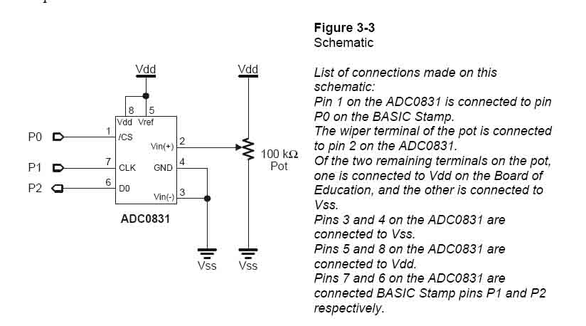
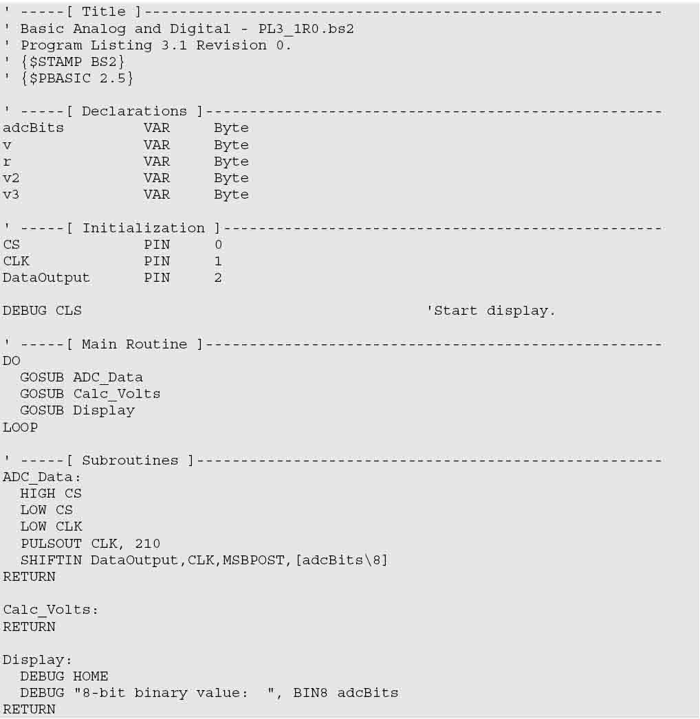
Recently I have a robotic project where need to control 8 pieces of Potentialmeter to my BS2 board, at such, I have found some related info and finally think ADC0831 can suit to my requirement (Refer Picture 1 and Picture 2), however, each ADC0831 required 3 input pins to BS2 board or in simply it needs (8 x 3) = 24 input pins, ·so I don’t think BS2 can have enough pin to handle this.
·
After I read through ADC0831 datasheet, I realized that another IC ADC0838 where it has 8 channels for single chip, but I really don’t know how to connect it to my stamp board as I try to search through the internet, does any could help to provide stamp code (BS2) ·and circuit connection diagram to me.
·
Your valued comment is greatly appreciated!
·
Best Regard,
·
Efly
·
Recently I have a robotic project where need to control 8 pieces of Potentialmeter to my BS2 board, at such, I have found some related info and finally think ADC0831 can suit to my requirement (Refer Picture 1 and Picture 2), however, each ADC0831 required 3 input pins to BS2 board or in simply it needs (8 x 3) = 24 input pins, ·so I don’t think BS2 can have enough pin to handle this.
·
After I read through ADC0831 datasheet, I realized that another IC ADC0838 where it has 8 channels for single chip, but I really don’t know how to connect it to my stamp board as I try to search through the internet, does any could help to provide stamp code (BS2) ·and circuit connection diagram to me.
·
Your valued comment is greatly appreciated!
·
Best Regard,
·
Efly
824 x 458 - 45K
1018 x 1046 - 63K
Comments
It has 11 input channels and 12-bit resolution.
' {$STAMP BS2}
' {$PBASIC 2.5}

' Test code for TLC1543CN 12-bit ADC. 11 analog inputs.
' --------------------------------------------------------------------------------------------

sclk PIN 1 ' clock out from BS2
sdo PIN 2 ' data from BS2 to ADC
sdi PIN 3 ' data to BS2
ADcs PIN 4 ' chip select, active low

ADch VAR Nib ' selects AD external channel 0-10
result VAR Word ' result, 12 bit A/D conversion

demo: ' to show off the subroutine below.

LOW ADcs
DO
  GOSUB ADwake ' makes a dummy conversion to initialize converter
  FOR ADch =0 TO 10 ' specify one of 11 input channels
    GOSUB ADread ' get millivolt data from that channel
    result = 14464 ** result + result ' convert count to millivolts.
    DEBUG DEC ADch,": ",DEC result,REP 32\5,CR ' display, use extra spaces to clear garbage
  NEXT
  GOSUB ADsleep
  'NAP 1
  DEBUG HOME ' repeat the demo
LOOP

ADread: ' entry point to give result as count from 0 to 4095
 LOW ADcs ' select chip
 SHIFTOUT sdo,sclk,MSBFIRST,[noparse][[/noparse]ADch<<8\12] ' mode, left justify ADch
 SHIFTIN sdi,sclk,MSBPRE,[noparse][[/noparse]result\12] ' get result, 12 bits
 HIGH ADcs ' deselect chip
RETURN

ADsleep: ' entry point to put TLC2543 to sleep
 LOW ADcs ' select chip
 SHIFTOUT sdo,sclk,MSBFIRST,[noparse][[/noparse]$e\4] ' command=$e
 HIGH ADcs ' deselect chip
 LOW sdi ' keep this pin from floating in sleep
RETURN

ADwake:
 ADch=$b
 GOTO ADread
▔▔▔▔▔▔▔▔▔▔▔▔▔▔▔▔▔▔▔▔▔▔▔▔
Don't worry. Be happy