

Basic Stamp 2 as a Fire Alarm Control Panel
 Tylerr96
Posts: 3
Tylerr96
Posts: 3
Hi,
I tried searching the forums, but didn't find anything on this topic.
How can I make a 24 volt Fire alarm control panel similar to this: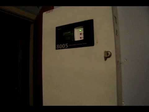 ?
?
I'd love to have one, I'm great with electronics (ok, exceptional at least...), just need a little help. I messaged the user, but either he was just not in the mood to help me or he didn't get the message. Either way it sounds like I'm going to need a Basic Stamp EDU board, some relays, a breadboard, and what else??
I've left alot out of this original post, but feel free to ask any more questions that could help you help me.
-Tyler
I tried searching the forums, but didn't find anything on this topic.
How can I make a 24 volt Fire alarm control panel similar to this:
?I'd love to have one, I'm great with electronics (ok, exceptional at least...), just need a little help. I messaged the user, but either he was just not in the mood to help me or he didn't get the message. Either way it sounds like I'm going to need a Basic Stamp EDU board, some relays, a breadboard, and what else??
I've left alot out of this original post, but feel free to ask any more questions that could help you help me.
-Tyler
Comments
There's also the Nuts and Volts Columns. Column #6 discusses controlling relays and solenoids.
Go to the main Parallax website and click on the "Resources" tab. You'll get a list. One item is a link to the Nuts and Volts index. Another is "Downloads". The tutorials are under "Stamps in Class Downloads" in "Downloads".
As shown in the Nuts and Volts Column, you'll need some transistors or transistor arrays to control relays. For sensing a 24V signal, you could use a 47K to 100K resistor in series with a Stamp I/O pin.
While this looks like a very worth wile project you need to concider a few things first:
1) Define exactaly what you want your Fire Alarm system to do. Check out the Codes and Standards section of the NFPA (National Fire Protection Association.)
·························· http://www.nfpa.org/categoryList.asp?categoryID=124&URL=Codes%20&%20Standards&cookie%5Ftest=1
··· They set the standards for fire prevention safety in the US.
2) Will you be willing to risk your life·with your project? The one you pointed out looks like it was wired on breadboard and not too high on the reliability ladder.
···· You would not only be risking your life but thoes family/friends/customers in your building.
···· Most electrical component data sheets state they are not intended to be used in life support systems. (Thats lawyers for you.)
3) False Alarms: Most citys/towns have a policy about false alarms, and you pay the cost of the second false alarm they respond to.
···· In our town (Canaan NH)·it costs about $1,500 to send out the volunteer fire dept. (About the price of a commerciual fire alarm unit)
I wanted to build my own Fire/Burgler/Freeze Alarm when·I built my new house 2 years ago. It is a piece of cake project for a Stamp.
I was going to use a PLC and Touch Screens as I had some left over units form a commercial project I did a few years prior, but the same applys to Stamps.
I have a freind who sells and installs alarm systems and he helped me look at the pitfalls.
Along with the technical issues noted above, your system may have to pass your local fire codes and insurance regulations.
Some of them have to do with reliability testing. If they have passed the NFPA testing then the inspectors look no more.
He sold me a system at his cost, and helped install it for free so I know he wasnt just looking for work, but wanted to help out.
Now having said that:
It is a cool project and if I didnt discourage you, then have fun.
Mike has steered you in the right direction for the 24 volt interfacing. It is real simple.
I have been interfacing Stamps to industrial machinery for 12 years.
The biggest problem to avoid is not looking at the Sensors/Inputs while you are doing something else.
You dont want to miss an alarm input.
I use a polling routine where I service the inputs, but dont get tied up waiting for things to happen.
If you need to pause for a few seconds then:
Wait_4_Somethinbg_To_Happen:
· pause 1
[noparse][[/noparse]Look at the input]
if X > Delay_Time then Somewhere_Else:
x=x+1 [noparse]:D[/noparse]elay Counter
goto Wait_4_Somethinbg_To_Happen:
That way you can wait and look at the same time.
Good Luck
▔▔▔▔▔▔▔▔▔▔▔▔▔▔▔▔▔▔▔▔▔▔▔▔
Alan Bradford ·N1YMQ
Plasma Technologies
Canaan NH 03741
www.plasmatechnologies.com
▔▔▔▔▔▔▔▔▔▔▔▔▔▔▔▔▔▔▔▔▔▔▔▔
- Stephen
Thank you for your reply. I realize the risks, and will also have "backup" smoke detectors just in case. It is more for experimentation purposes than anything, and if I get it completely flattened out and working flawlessly, I may use it primarily...
And thanks to everyone elses replies, I'll have a look at the tutorials a little later...
Thanks,
Tyler
Take a look at it, I think it would work well for You, and this project.
_________$WMc%_________
▔▔▔▔▔▔▔▔▔▔▔▔▔▔▔▔▔▔▔▔▔▔▔▔
The Truth is out there············································ BoogerWoods, FL. USA
*LCD Displays
*Relays (for horns/strobes)
*Terminal strips (this is pretty simple, right?)
*How to change the Voltage to 24 DC
Why do they use two breadboards? They use the one thats built into the board of education carrier and they have another one in addition...Why?
And, if I could save money, I'm not going to buy a BS2PLC...but thanks for the suggestion!
And I'm assuming that pull stations are just Normally Open circuits, so I don't need anything between those and the board, right? No relay, resistor... But smoke/heat detectors are different because they require power...
Thanks,
Tyler
▔▔▔▔▔▔▔▔▔▔▔▔▔▔▔▔▔▔▔▔▔▔▔▔
- Stephen