Convert AC to DC
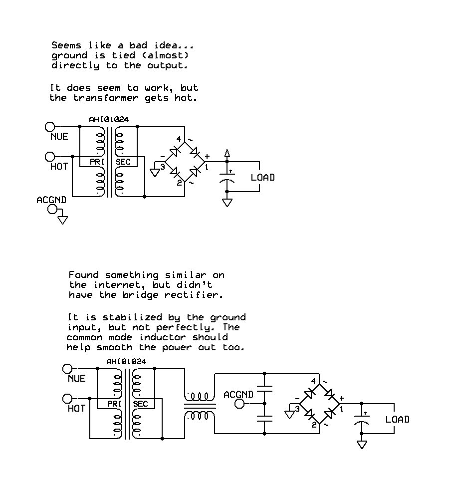
I need to convert a 120V AC to 12V DC. I have a Zettler AHI01024 transformer (120/240V to 24/12V). It has has 4 connectors on each side of the transformer. I also have a common mode inductor. Attached is a couple guess as to how to wire it up (based on some random stuff on the net). I am looking to provide non-isolated DC power. What is the best way to provide stable power that is the negative side of the DC output is grounded (directly to earth ground. I am regulating the power down to a lower voltage (that 12V) with a linear/LDO regulator. Maybe if I use the common on the regulator to reference the input ground (I think that will work either)....
Am I on the right path? Or am I going to fry my transformer. What is the best way to supply grounded DC power from a AC power source?
▔▔▔▔▔▔▔▔▔▔▔▔▔▔▔▔▔▔▔▔▔▔▔▔
April, 2008: when I discovered the answers to all my micro-computational-botherations!
Am I on the right path? Or am I going to fry my transformer. What is the best way to supply grounded DC power from a AC power source?
▔▔▔▔▔▔▔▔▔▔▔▔▔▔▔▔▔▔▔▔▔▔▔▔
April, 2008: when I discovered the answers to all my micro-computational-botherations!


Comments
Some additional information: I have tested the second diagram in that image. I used 2 6.8µF caps (tied to AC ground), 16mH common mode inductor, and a 1000µF along with the load. No matter how much load I gave it (I tested between 1000-ohm and 20-ohm) it gives about a 1V fluctuation (relative to ground -- not great, but acceptable as it is going to be regulated down). But that wiring setup is not tied to ground.
▔▔▔▔▔▔▔▔▔▔▔▔▔▔▔▔▔▔▔▔▔▔▔▔
April, 2008: when I discovered the answers to all my micro-computational-botherations!
How much current are you drawing? What's the rating of the transformer windings?
A 1000uF capacitor across the output sounds about right. What's the capacitor's voltage rating?
But if that shouldn't be bad for anything, then I guess I already have my solution.
▔▔▔▔▔▔▔▔▔▔▔▔▔▔▔▔▔▔▔▔▔▔▔▔
April, 2008: when I discovered the answers to all my micro-computational-botherations!
Paralleling these windings should be fine. They're designed to be identical so you can connect them in series for 240VAC or in parallel for 120VAC with double the current handling capacity. Similarly with the secondaries, they're designed to be connected in parallel (for 24VAC) or in series (for 12VAC).
The transformer should get fairly warm at load. With 20 Ohms' load and probably 14-16VDC output, you're running close to full rating. A bridge rectifier runs hotter than a half-wave rectifier because the bridge is conducting on both half cycles and the extra 1.4V drop across the rectifier takes a little more "juice" from the transformer.