Shop OBEX P1 Docs P2 Docs Learn Events
PIR to trigger 555 timer — Parallax Forums

PIR to trigger 555 timer

dev/nulldev/null Posts: 381
edited 2009-07-23 19:19 in Accessories
Hi

I want the PIR to trigger the input of a 555 timer to set of a relay. In the circuit below, a switch (S1) is used to trigger it.
How can I connect the PIR to this circuit to trigger the timer? (U1 is a 555 timer)
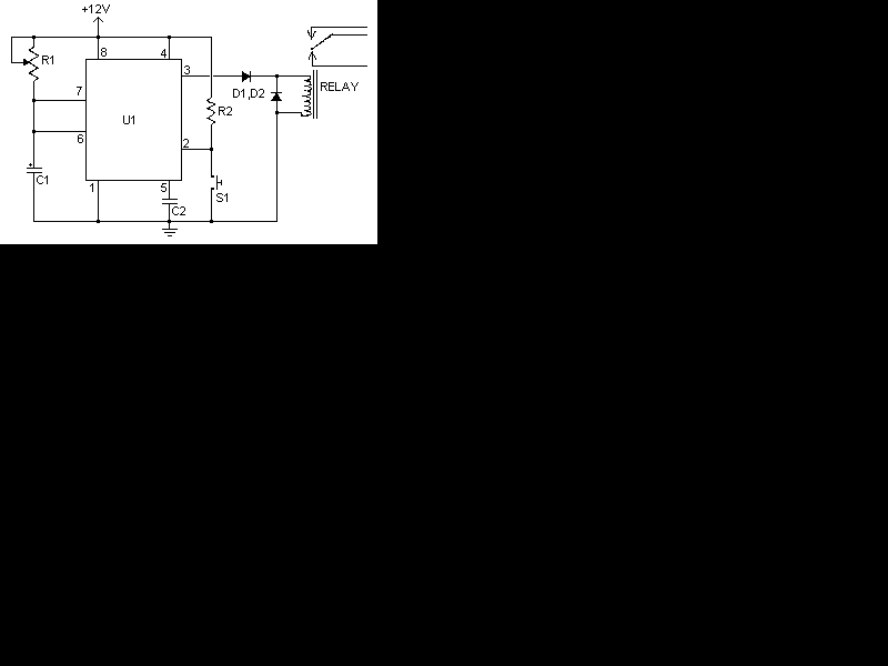
relaytim.gif

I have an appropriate voltage regulator (7805) going to the PIR.

Thanks.

▔▔▔▔▔▔▔▔▔▔▔▔▔▔▔▔▔▔▔▔▔▔▔▔
Don't worry. Be happy

Comments

  • PrettybirdPrettybird Posts: 269
    edited 2009-07-21 18:42
    Not sure of the term PIR but looks like a one shot circuit. I would knock down the 555 supply to 5v and use a transistor to turn on the relay at 12v You can run a 5v signal then for sure. Or use an optic isolater as a switch.
  • dev/nulldev/null Posts: 381
    edited 2009-07-21 18:59
    The PIR is a movement sensor. It has a signal output that goes high when there is movement. I got the circuit working with an NPN in the S1 junction (except for the relay voltage problem).
    Thanks for the tip about voltage. I just ordered 3V SSR relays because of this, which I could have saved. But then again, now I have some SSR relays smile.gif

    ▔▔▔▔▔▔▔▔▔▔▔▔▔▔▔▔▔▔▔▔▔▔▔▔
    Don't worry. Be happy
  • VelocitVelocit Posts: 119
    edited 2009-07-21 23:11
    I would leave the 555 at +12V. The NPN can be saturated by +5V while isolating the PIR sensor from +12V. The only thing to be aware of is the risk of the transistor failing, in which case +12V could reach the PIR sensor.

    ▔▔▔▔▔▔▔▔▔▔▔▔▔▔▔▔▔▔▔▔▔▔▔▔
    -Paul
  • SRLMSRLM Posts: 5,045
    edited 2009-07-22 03:25
    I'm a novice EE, but this link may help some.
  • PrettybirdPrettybird Posts: 269
    edited 2009-07-22 14:48
    OK is see now. Different english. I have a generic ultrasonic sensor the sounds similar. Low until triggered. If the relay is properly clamped with a diode and a little below the max for the transistor it should last forever. Transistors are alot tougher then ICs. Not sure what you are doing but the switch is a normally open switch. High to low. Opposite what you described of your device (reverse logic). Electronics shematics much easier then talking it for me. Lingo changes but parts stay the same. lol
  • dev/nulldev/null Posts: 381
    edited 2009-07-22 18:27
    Here is my new circuit:
    crk2.jpg

    Problem is, I get only 3.5V out from the T2 emitter.
    (if I use 5V for the whole circuit, it works with a LED)

    What could be the problem?

    ▔▔▔▔▔▔▔▔▔▔▔▔▔▔▔▔▔▔▔▔▔▔▔▔
    Don't worry. Be happy
  • VelocitVelocit Posts: 119
    edited 2009-07-22 18:56
    T2 is backward, the emitter should be connected to +12V. You probably don't even need T2 depending on your relay. Standard 555's can source or sink up to 200mA. That should be plenty of current for many relays. Do you know the coil characteristics of yours?

    Also, the 555's monostable output is active high. The transistor is effectively inverting the signal from the 555 and only tripping the relay while the timer isn't triggered.

    T1 should be an NPN transistor with the emitter connected to ground. You currently have it as a PNP transistor.

    I would seriously consider putting the 555 back on +12V and just using an NPN transistor in place of S1 in your original schematic.

    ▔▔▔▔▔▔▔▔▔▔▔▔▔▔▔▔▔▔▔▔▔▔▔▔
    -Paul
  • dev/nulldev/null Posts: 381
    edited 2009-07-22 19:07
    Actually, it's an NPN transistor, I wrote it wrong in the schematics.
    Here is an updated schematic. Can you revisit and tell me again what's wrong?
    Thanks a lot.
    crk4.jpg

    ▔▔▔▔▔▔▔▔▔▔▔▔▔▔▔▔▔▔▔▔▔▔▔▔
    Don't worry. Be happy
  • dev/nulldev/null Posts: 381
    edited 2009-07-22 19:14
    If I put a LED instead of a relay there, the schematic works....

    ▔▔▔▔▔▔▔▔▔▔▔▔▔▔▔▔▔▔▔▔▔▔▔▔
    Don't worry. Be happy
  • VelocitVelocit Posts: 119
    edited 2009-07-22 19:19
    What are the characteristics of the relay's coil? I assume its nominal voltage is 12VDC, correct? How much current does it require?

    ▔▔▔▔▔▔▔▔▔▔▔▔▔▔▔▔▔▔▔▔▔▔▔▔
    -Paul
  • dev/nulldev/null Posts: 381
    edited 2009-07-22 19:20
    Proper circuit:
    crk5.jpg

    ▔▔▔▔▔▔▔▔▔▔▔▔▔▔▔▔▔▔▔▔▔▔▔▔
    Don't worry. Be happy
  • dev/nulldev/null Posts: 381
    edited 2009-07-22 19:21
    It's 12V. I think 200mA, but not sure.

    ▔▔▔▔▔▔▔▔▔▔▔▔▔▔▔▔▔▔▔▔▔▔▔▔
    Don't worry. Be happy
  • phil kennyphil kenny Posts: 233
    edited 2009-07-22 19:55
    T2 is connected as an emitter follower. As such, the emitter will always
    be 0.7 volts below the base voltage. That's why you don't get more than
    3.5 volts at T2 emitter.

    You should change T2 so that the emitter is grounded and move the
    relay coil and D2 to the collector of T2.

    Delete D1 since it isn't necessary.

    phil
  • dev/nulldev/null Posts: 381
    edited 2009-07-22 20:52
    Sorry for being such a noob. Here is the final schematics. Works perfect. This will control lighting in my doorway.
    I will post the complete project once I'm finished.

    crk7.jpg

    Thanks for all the help.

    ▔▔▔▔▔▔▔▔▔▔▔▔▔▔▔▔▔▔▔▔▔▔▔▔
    Don't worry. Be happy
  • PrettybirdPrettybird Posts: 269
    edited 2009-07-23 05:45
    Good job. Not sure you need the transistor on the PIR but as long as it works. Data sheets are great for experimenting, designing. I did a similar thing years ago using a toy car R/C and had a JK flip flop before the relay to turn lights on and off. Sort of like a wireless clapper. I used 2 channels for 2 appliances. This was long before the Basic stamp.
  • dev/nulldev/null Posts: 381
    edited 2009-07-23 16:01
    Thanks. I just installed the thing on my wall, and it works there too smile.gif
    The PIR sensor needs some time to settle, so in the beg. I thought it wasn't working, but after a while it works perfectly.

    ▔▔▔▔▔▔▔▔▔▔▔▔▔▔▔▔▔▔▔▔▔▔▔▔
    Don't worry. Be happy
  • dev/nulldev/null Posts: 381
    edited 2009-07-23 16:14
    Here is a link to the completed project: http://forums.parallax.com/showthread.php?p=826065

    ▔▔▔▔▔▔▔▔▔▔▔▔▔▔▔▔▔▔▔▔▔▔▔▔
    Don't worry. Be happy
  • PrettybirdPrettybird Posts: 269
    edited 2009-07-23 19:19
    It is probally similar to the generic ultrasonic sensor I have laying around.
Sign In or Register to comment.