

Noise Problem Driving Relay
 everest
Posts: 141
everest
Posts: 141
All,
I'm creating a PC controller relay board with my Stamp2 and I'm running into a strange "noise" problem. . .at least I think it must be noise. Here's the problem:
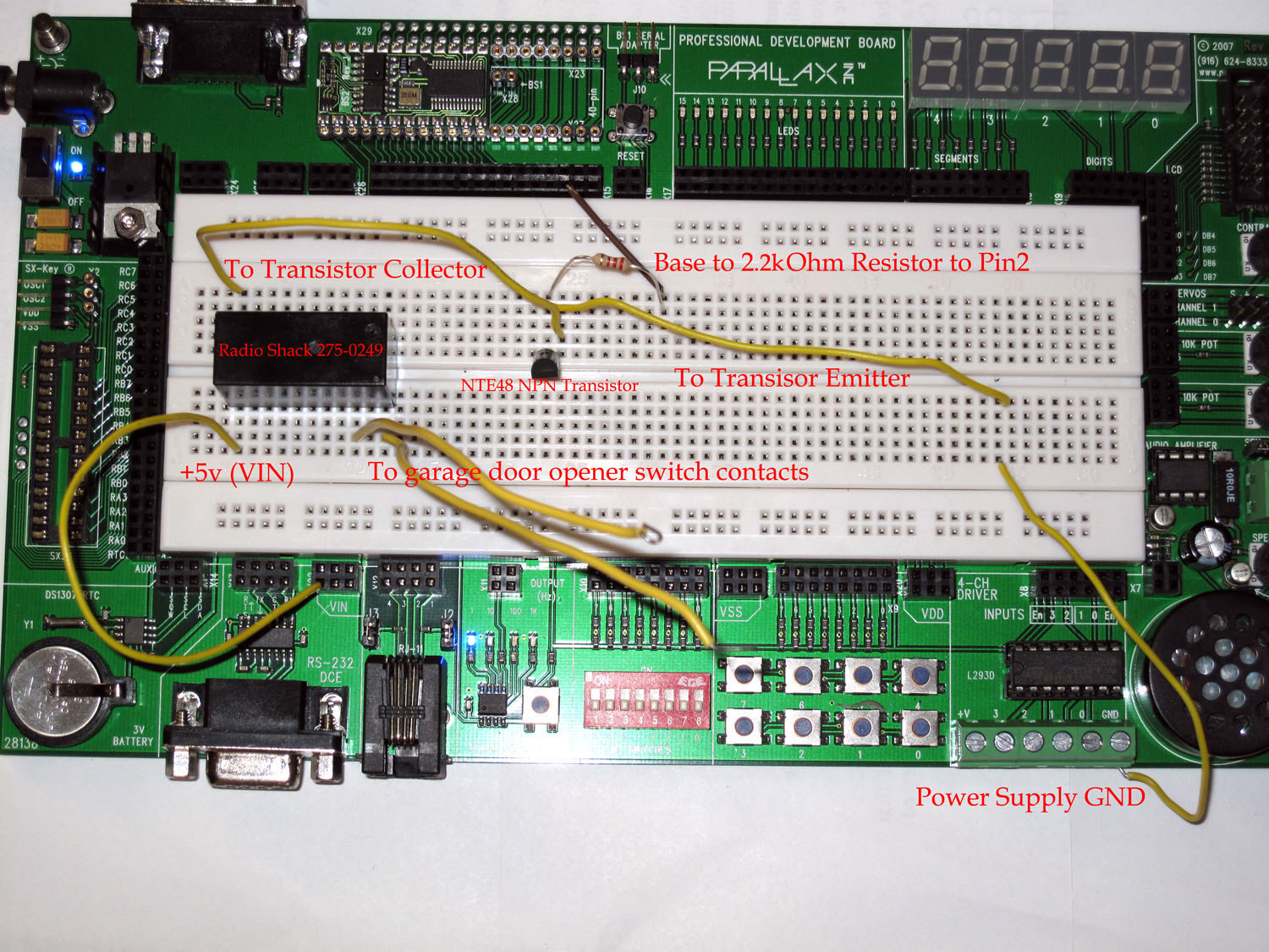
1) I've attached a photo that illustrates the circuit I'm using. If I create this circuit as shows on the breadboard, it works fine.
2) For "production" I have created a dedicated project box that leverages a Cat5 cable to run VIN, GND, and three pins to/from the Stamp2 module
PROBLEM: Wired as shown on the breadboard it works fine. When using the Cat5 to run out to my relay box, the relays "chatter" when the Stamp2 Pin connected to the base on the transistor is LOW. When I take the pins HIGH the relay closes just fine. . .but the "chatter" bothers me. . .relays shouldn't vibrate like that. I have no idea why this is happening. . .can anyone help me?
I've attached photos of the circuit on a development board. I'll follow up with a photo of the "production unit" that shows the Cat5 cable.
Here's some sample code that simply cycles pin0 high/low. As I've said, on the production unit the relay vibrates/hums when the pin is low. . .and I want that to stop. Any suggestions would be much appreciated. Thanks!
-Jeff
**** Super simple code *******
' {$STAMP BS2}
' {$PBASIC 2.5}
OUTPUT 0
Main:
PAUSE 1000
HIGH 0
PAUSE 500
LOW 0
PAUSE 500
GOTO Main
Post Edited (everest) : 7/5/2009 5:24:21 PM GMT
I'm creating a PC controller relay board with my Stamp2 and I'm running into a strange "noise" problem. . .at least I think it must be noise. Here's the problem:
1) I've attached a photo that illustrates the circuit I'm using. If I create this circuit as shows on the breadboard, it works fine.
2) For "production" I have created a dedicated project box that leverages a Cat5 cable to run VIN, GND, and three pins to/from the Stamp2 module
PROBLEM: Wired as shown on the breadboard it works fine. When using the Cat5 to run out to my relay box, the relays "chatter" when the Stamp2 Pin connected to the base on the transistor is LOW. When I take the pins HIGH the relay closes just fine. . .but the "chatter" bothers me. . .relays shouldn't vibrate like that. I have no idea why this is happening. . .can anyone help me?
I've attached photos of the circuit on a development board. I'll follow up with a photo of the "production unit" that shows the Cat5 cable.
Here's some sample code that simply cycles pin0 high/low. As I've said, on the production unit the relay vibrates/hums when the pin is low. . .and I want that to stop. Any suggestions would be much appreciated. Thanks!
-Jeff
**** Super simple code *******
' {$STAMP BS2}
' {$PBASIC 2.5}
OUTPUT 0
Main:
PAUSE 1000
HIGH 0
PAUSE 500
LOW 0
PAUSE 500
GOTO Main
Post Edited (everest) : 7/5/2009 5:24:21 PM GMT
1500 x 1125 - 422K
Comments
-Jeff
Take a few minutes and generate a schematic for us. Particularly, what's in the box and where does the CAT5 go ?
A couple of things right off is the (apparent ) lack of a diode across the relay coil to control the inductive voltage when the relay releases.
Also, using CAT 5 is fine but you have to remember to use the twisted pairs as pairs to minimize the coupling of spikes from one conductor to another.
The chatter/hum when the Stamp pin is low is troubling as the transistor is off at that point so if the hum is there, it means something is forcing that pin high against its will.
▔▔▔▔▔▔▔▔▔▔▔▔▔▔▔▔▔▔▔▔▔▔▔▔
Tom Sisk
http://www.siskconsult.com
·
DPDT 5A at 240VAC/24VDC
Nominal coil rating of 12VDC, maximum 15.6VDC
** Pickup/dropout voltage 9.6/0.6VDC **
Nominal coil current 60mA
You may be operating the relay more like a buzzer?
hth
- H
▔▔▔▔▔▔▔▔▔▔▔▔▔▔▔▔▔▔▔▔▔▔▔▔
How long is the cat 5 cable your running?
If it is too long it may be dropping too much voltage to activate the relay.
But the Pause stastements would make it only try every 1/2 second.
I think your problem may be a wiring mistake in the production unit.
Are you using an AC to DC power supply?
If the transistor turning on causes a short it may be resetting the Stamp...Except for the Pause statements again!
I would first try to use the breadboard and the cat 5 cable to rule that out.
Then I would look at the power supply closely (if it is an AC supply)
What are the contacts of the relay switching?
If that circuit is running from the same power supply, and shorting the PS then it would make the relay buzz.
The voltage energizes the coil , closing the contacts, causing a short, causing the voltage to drop and denergizing the coil, removing the short, causing the voltage to go up,, energizing the coil........
Voila....Instant Buzzer. Been there and have lots of the t-shirts!
Try disconnecting the load from the realy contacts.
Good luck,
Alan Bradford
Plasma Technologies
www.plasmatechnologies.com
▔▔▔▔▔▔▔▔▔▔▔▔▔▔▔▔▔▔▔▔▔▔▔▔
Alan Bradford ·N1YMQ
Plasma Technologies
Canaan NH 03741
www.plasmatechnologies.com
Thanks for the info. . .here's the weird part. I don't think this has anything to do with the Stamp2. The relays will "buzz" when I even *touch* the wires that connect to the Stamp2 pins. I can disconnect the Stamp2 pin, and if I hold the Cat5 wire in my fingers, the relays start buzzing!! They don't even have to be connected!?!?! For clarification, the relays CLOSE just fine. When I take the pins high, the relay snaps closed with no problems. It's when I take the Stamp2 pin low that it starts to buzz. Rather than just going into a state where the relay is open, it buzzes like it's trying to close! Note that the relays don't have loads connected at this point, there is nothing connected. I just can't figure this out for the life of me.
I'm suspecting that it must be the Cat5 cable at this point. . .something is screwy. I'm going to try a straight phone line (no twisted pairs) and see what affect if any that has.
-Jeff
-J
There's very little way to help you without a detailed description of what is wired to what and the best way to do that is with a drawing.
▔▔▔▔▔▔▔▔▔▔▔▔▔▔▔▔▔▔▔▔▔▔▔▔
Ain't gadetry a wonderful thing?
aka G. Herzog [noparse][[/noparse] 黃鶴 ] in Taiwan
Even when I just wire this up straight on the development board, if I touch the resistor or diode and touch the metal. . .the relay immediately starts to buzz like crazy, again only if the Stamp2 pin is LOW. If it's high the relay snaps closed and the buzzing stops.
Any suggestions though would be much appreciated. Thanks!
-Jeff
Another source of the chatter may be inductive electricity from something like flourescent lights as the Darlington is high gain. It may require a pull down resistor in order to remain fully off. You really should avoid a long wire from the BasicStamp to the Darlington base as this works as an antenna. If you need a cable, it should be from the +12 and the transistor's collector.
Pls forgive the gripe, I am happy to help as I want to build something similar and am worried about mysterious chatter.
▔▔▔▔▔▔▔▔▔▔▔▔▔▔▔▔▔▔▔▔▔▔▔▔
Ain't gadetry a wonderful thing?
aka G. Herzog [noparse][[/noparse] 黃鶴 ] in Taiwan
Post Edited (Loopy Byteloose) : 7/6/2009 5:52:27 AM GMT
▔▔▔▔▔▔▔▔▔▔▔▔▔▔▔▔▔▔▔▔▔▔▔▔
Ain't gadetry a wonderful thing?
aka G. Herzog [noparse][[/noparse] 黃鶴 ] in Taiwan
I think Loopy Byteloose is correct in that you can't drive a 12v relay with a 5v supply.
▔▔▔▔▔▔▔▔▔▔▔▔▔▔▔▔▔▔▔▔▔▔▔▔
EverQurious
Post Edited (EverQurious) : 7/6/2009 6:11:57 AM GMT
-Jeff
By using a Darlington, an on condition requires extemely low current - the region of micro amps. And so that is where the sensitivity to noise creeps in.
▔▔▔▔▔▔▔▔▔▔▔▔▔▔▔▔▔▔▔▔▔▔▔▔
Ain't gadetry a wonderful thing?
aka G. Herzog [noparse][[/noparse] 黃鶴 ] in Taiwan
Sun Microsystems has sponsored a project called Open Office, which is an alternative to Microsoft Office. There two great aspects about Open Office: 1) it works, and 2) it's a free download. If you wish to add that it has compatibility with Microsoft Office, then there's three neat things about it.
Included in Open Office is the Drawing application that may fill your needs. The other applications are:
Text Document (Word)
Presentation (Power Point)
Database (Access)
Spreadsheet (Xcel)
Drawing (drawing tool, don't know if MS Office has a counterpart outside of Word)
Formula (formula editor, don't know if MS Office has a counterpart)
You can find this package at www.openoffice.org - it's between 200 - 300meg big.
Regards,
DJ
▔▔▔▔▔▔▔▔▔▔▔▔▔▔▔▔▔▔▔▔▔▔▔▔
Instead of:
"Those who can, do.· Those who can't, teach." (Shaw)
I prefer:
"Those who know, do.· Those who understand, teach." (Aristotle)
·
When the stamp pin goes low it does not pull the base of the transistor to ground.
The diode is not required, get rid of it.
- H
▔▔▔▔▔▔▔▔▔▔▔▔▔▔▔▔▔▔▔▔▔▔▔▔
But you still have the 1.2 to 1.4v drop by using a Darlington transistor. A normal transistor has only a 0.6-0.7v drop. Trying to provide a 12v relay from a 12v supply with a Darlington pair is a bit dicey. So you may have to decide if you want a 13.2volt supply or forgot the high gain of the Darlington. If you really must have high gain, use a 2n7000 mosfet instead and you also won't have to deal with the voltage drop issue. A 12v power supply will be fine. The mosfet will likely work fine with the 2500 resistor to the gate.
Eagle CAD will draw the schematics, has a good library of componets, and even route a small board for free. I have Open Office, but I rarely use the Draw feature as it is a hassle to draw transistors, resistors and capacitors. Parallax SPIN provides a font that will draw all these quite easily in text.
▔▔▔▔▔▔▔▔▔▔▔▔▔▔▔▔▔▔▔▔▔▔▔▔
Ain't gadetry a wonderful thing?
aka G. Herzog [noparse][[/noparse] 黃鶴 ] in Taiwan
Post Edited (Loopy Byteloose) : 7/6/2009 3:12:57 PM GMT
Thanks for all the suggestions. I strongly suspect that the transistor is the issue here. . .removing the diode doesn't solve the issue. In fact, I disconnected from the Stamp entirely and noticed some strange behavior. . .after energizing the relay, the transistor I'm using will still allow current to flow even after disconnecting the base entirely! Obviously it closes when I disconnect the ground, and then after reconnecting the ground it will not open again, until I connect it back to stamp and take the Pin HIGH. At that point even disconnecting entirely from the Stamp won't stop that transistor from letting current flow!!
I've seen some schematics posted with different kinds of transistors, I'm going to stop chasing my tail with this and just use some "proven" components. Thanks everyone!
-Jeff
This was on my 4th Board...But it's the 1st SMT Board of the same project.
So to all BEGINNERS!!! and me
Watch your wiring layout of (((whats near what line(s) and what crosses what line(s))))....The boards had a host of other problems that I fixed, but that one was a da da!!! $83.00 (3 boards) wasted...New Boards came up first time...Ya Ho
▔▔▔▔▔▔▔▔▔▔▔▔▔▔▔▔▔▔▔▔▔▔▔▔
I'M STILL LEARNING SO MUCH...BUT STILL KNOW SO LITTLE!!!
hmlittle59
Post Edited (hmlittle59) : 7/6/2009 10:15:42 PM GMT
In this case, you have a rather long wire acting as an antenna on the finished product - not good. It would be better to have the long wire on the 12volt output to rela
When I try to research Darlington Transistor Relay drivers, I cannot locate any example schematics. It appears that most designers avoid them and either use a 2n3904, 2n2222, or if more current is required, they use a MOSfet.
Increasing the power supply to 13.2volts should indicate if the added voltage drop of the Darlington pair is the problem. With the increase, the problem may disappear. If it doesn't disappear, it is likely the high gain on the input side.
▔▔▔▔▔▔▔▔▔▔▔▔▔▔▔▔▔▔▔▔▔▔▔▔
Ain't gadetry a wonderful thing?
aka G. Herzog [noparse][[/noparse] 黃鶴 ] in Taiwan
Post Edited (Loopy Byteloose) : 7/7/2009 8:36:34 AM GMT
I wrote this tutorial on relays if you're interested:
http://www.societyofrobots.com/member_tutorials/node/187
Post Edited (ceruleanplains) : 7/7/2009 11:49:32 AM GMT
My local Radio Shack didn't have any 2n2222's in stock, but they did have some MPS2222A, and at .79 I decided to give them a try. They work perfectly!! No noise, no flutter at all! Thanks again for all the suggestions. I guess I should just stick to proven parts!
-Jeff
A lot of the OLDER 2NXXXX JEDEC (Joint Electron Device Engineering Council) style names have also transformed into many transistors with the same numbers and specifications just different prefixes (for US style transistors)
The high gain of a darlington has its place... but when you just need a "switch", the 2N2222 is great. Lets look at it this way. It was introduced in 1962... and they still make them.
en.wikipedia.org/wiki/2N2222
▔▔▔▔▔▔▔▔▔▔▔▔▔▔▔▔▔▔▔▔▔▔▔▔
There's nothing like a new idea and a warm soldering iron.
You can even export stuff to Spice, and run it in Mathematica or some other analyzer if you want.
▔▔▔▔▔▔▔▔▔▔▔▔▔▔▔▔▔▔▔▔▔▔▔▔
Don't worry. Be happy